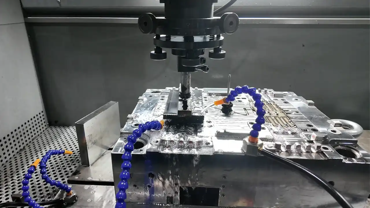
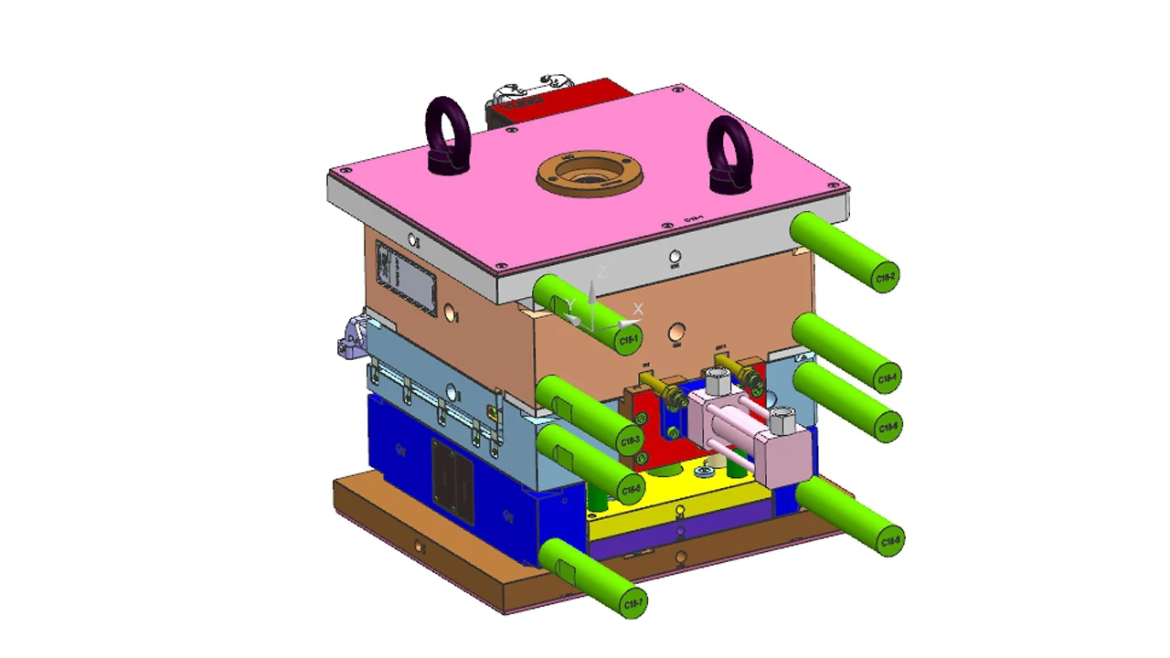
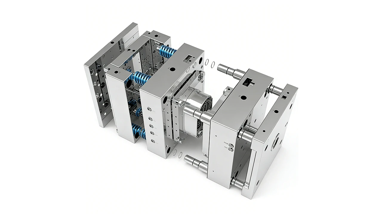
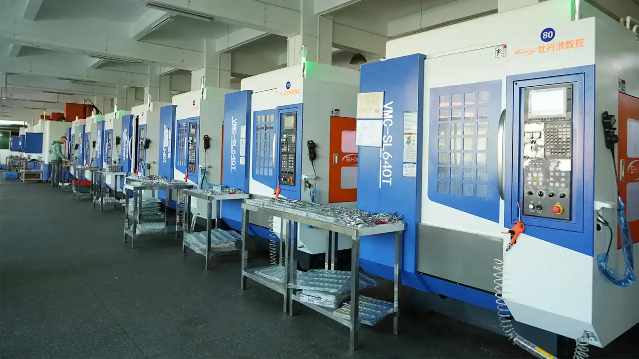
High-density polyethylene is one of the most cost-effective, chemically resistant, and impact-tough thermoplastics available for injection molding — yet its high shrinkage and warpage tendency trips up engineers who do not design for it from the start. This guide covers everything you need to know: material science, processing parameters, mold design, grade selection, and real-world applications — so you can specify and manufacture HDPE parts with confidence.
What Is HDPE Plastic?
High-density polyethylene — abbreviated HDPE — is a semi-crystalline thermoplastic polymer produced through the polymerization of ethylene monomers under controlled conditions of pressure and catalysis. The “high-density” designation refers to the tightly packed, linear molecular chain structure that gives this resin its defining combination of rigidity, strength, and chemical inertness.
With a global market valued at approximately $84.3 billion in 2024 and projected to reach $116.8 billion by 2033 (IMARC Group), HDPE ranks among the most produced and widely recycled plastics on earth. It sits in the commodity thermoplastic tier alongside PP and PVC — but its performance-to-cost ratio frequently makes it the go-to choice for applications where engineering plastics would be over-specified and under-resourced materials would fail prematurely.
HDPE carries resin identification code #2 and is classified within the broader polyethylene family:
Polyethylene Type
Density
Crystallinity
Typical Use
LDPE
0.910–0.940 g/cm³
~45%
Flexible packaging, film
LLDPE
0.915–0.940 g/cm³
~50%
Stretch film, flexible tubing
HDPE
0.941–0.965 g/cm³
~70–80%
Rigid containers, pipe, industrial parts
UHMW-PE
0.930–0.935 g/cm³
~50%
Wear liners, heavy-duty components
The higher crystallinity of this resin relative to LDPE is what drives its superior stiffness, chemical resistance, and barrier properties — and also its more challenging shrinkage behavior in injection molding.
The Molecular Structure Behind HDPE's Performance
Understanding why HDPE behaves the way it does in processing starts at the molecular level. Unlike LDPE — which contains abundant short- and long-chain branches that disrupt close packing — high-density polyethylene consists predominantly of linear, unbranched polymer chains. These chains align tightly during solidification, forming crystalline lamellae structures that account for 70–80% of the material’s volume.
This high degree of crystallinity directly governs several of the resin’s most important engineering properties:
Chemical resistance: Dense, ordered chain packing provides minimal pathways for solvent molecules to penetrate the polymer matrix
Impact toughness: The amorphous regions between crystalline domains absorb energy under impact without brittle fracture
Barrier performance: Low gas and moisture permeability relative to amorphous polymers of comparable density
High shrinkage: Significant volumetric contraction during crystallization — the primary source of HDPE’s dimensional challenges in injection molding
Molecular weight is the second critical structural variable. HDPE resin is commercially available across a broad molecular weight spectrum:
Standard MW grades (Mn ~50,000–150,000 g/mol): High melt flow index (MFI > 6 g/10 min), suited to injection molding
High MW grades (HMW-HDPE): Lower MFI, better impact and ESCR performance, more challenging to process
Ultra-high molecular weight (UHMW-PE, Mn > 1,000,000 g/mol): Cannot be injection molded by standard means; requires compression molding or ram extrusion
For injection molding applications, grades with MFI of 5–20 g/10 min represent the standard processing range.
Key Properties of HDPE Plastic
Mechanical Properties
Property
Typical Value
Unit
Tensile strength at yield
21 – 37
MPa
Elongation at break
300 – 1,000
%
Flexural modulus
900 – 1,500
MPa
Izod impact strength (notched)
50 – 200
J/m
Rockwell hardness
R60 – R70
—
Tensile modulus
700 – 1,400
MPa
A key mechanical characteristic of high-density polyethylene is its ductile failure mode — rather than fracturing catastrophically under impact, it deforms plastically, absorbing substantial energy before failure. This makes it well-suited to applications involving repeated mechanical loads, drop impacts, and rough handling in field conditions.
One critical design consideration: notch sensitivity. Sharp internal corners and abrupt section changes act as stress concentrators that significantly reduce the resin’s impact performance in practice. At Dimud, our mold engineering team consistently applies a minimum internal radius of 0.5 × wall thickness as a baseline rule for structural HDPE parts — a small change that substantially extends part service life.
Thermal Properties
Property
Value
Unit
Melting point
125 – 135
°C
Heat deflection temperature (0.45 MPa)
60 – 82
°C
Heat deflection temperature (1.80 MPa)
43 – 60
°C
Vicat softening point
125 – 130
°C
Continuous service temperature
up to 80
°C
Coefficient of thermal expansion (CTE)
100 – 200 × 10⁻⁶
/°C
The relatively modest heat deflection temperature of this material is one of its important limitations. Applications requiring sustained loads above 60–70°C should be evaluated carefully — or alternative materials such as PP, PA, or glass-filled grades considered. The high CTE value also has direct implications for mold shrinkage prediction and part tolerance specification.
Physical and Barrier Properties
Property
Value
Unit
Density
0.941 – 0.965
g/cm³
Water absorption (24 hr)
< 0.01
%
Mold shrinkage
1.5 – 3.5
%
Oxygen transmission rate (OTR)
Low
—
Moisture vapor transmission rate
Very low
—
Refractive index
1.54
—
HDPE’s near-zero water absorption (< 0.01%) is a significant processing advantage: standard grades do not require pre-drying before injection molding, reducing cycle preparation time and eliminating the risk of moisture-induced splay, silver streaking, or degradation in the melt.
The high mold shrinkage range of 1.5–3.5% is the resin’s most consequential processing characteristic. This shrinkage is both higher in absolute magnitude and more variable than most engineering thermoplastics — and its anisotropic nature is the root cause of the warpage challenges engineers frequently encounter with high-density polyethylene. We address this in detail in the processing section below.
Chemical Resistance
Chemical resistance is arguably HDPE’s strongest commercial attribute. The resin demonstrates outstanding resistance across a wide range of environments:
Excellent resistance (no significant attack):
Dilute and concentrated inorganic acids (HCl, H₂SO₄, HNO₃ at moderate concentration and temperature)
Strong alkalis (NaOH, KOH at all concentrations)
Aqueous salt solutions
Alcohols, aldehydes, and aqueous detergents
Animal and vegetable fats, oils, and greases
Limited resistance (evaluate by grade and conditions):
Aromatic hydrocarbons (toluene, xylene) — swelling and stress cracking risk
HDPE’s most treacherous failure mode is environmental stress cracking (ESC). This occurs when the resin is simultaneously exposed to a chemical agent (particularly surfactants, certain oils, and polar solvents) and mechanical stress — even well below the material’s yield point. The chemical does not dissolve the polymer; instead, it accelerates disentanglement of amorphous chain segments, producing brittle fracture in a material that would otherwise fail ductilely.
For chemical-contact applications under mechanical load, high-MW HDPE grades with ESCR (PENT test) values exceeding 1,000 hours are standard. Grade selection must explicitly address ESCR — bulk chemical resistance tables alone are insufficient.
Electrical Properties
Property
Value
Unit
Volume resistivity
> 10¹⁶
Ω·cm
Dielectric strength
18 – 30
kV/mm
Dielectric constant (1 MHz)
2.3 – 2.4
—
Dissipation factor (1 MHz)
< 0.0005
—
HDPE’s extremely low dissipation factor makes it one of the stronger commodity plastics for high-frequency electrical applications. Its electrical properties are essentially unaffected by moisture — a meaningful advantage over hygroscopic engineering polymers like PA and PC.
HDPE Plastic Injection Molding: Processing Parameters and Mold Design
Processing HDPE successfully requires disciplined attention to both machine parameters and mold design. The material’s high shrinkage and crystallization-driven behavior mean that problems rooted in mold geometry cannot be fully corrected through process adjustment alone.
Drying Requirements
Standard injection-molding grades absorb less than 0.01% moisture — pre-drying is not required under normal storage conditions. If resin has been stored in open containers in high-humidity environments, drying at 70–80°C for 1–2 hours prevents surface splay and silver streaking.
Melt Temperature
The recommended melt temperature range for HDPE injection molding is 200–280°C, with most grades processed at 220–260°C:
For flat or large-area HDPE parts with tight tolerances, 50–70°C mold temperature with uniform cooling channel distribution is standard practice at Dimud. Asymmetric mold temperatures are a frequently underappreciated driver of post-mold warpage.
Injection Pressure and Speed
Parameter
Recommended Range
Injection pressure
70 – 140 MPa
Holding pressure
50 – 80% of injection pressure
Holding time
10 – 30 seconds
Injection speed
Medium
Back pressure
5 – 15 MPa
Screw speed
40 – 80 RPM
High-density polyethylene melt is shear-sensitive — excessive injection speed causes melt fracture, visible as surface roughness. Medium fill speeds with adequately sized gates are preferred over high-speed injection.
Managing HDPE Shrinkage and Warpage
HDPE mold shrinkage of 1.5–3.5% is both high and highly variable. Key contributing factors:
Anisotropic shrinkage: The polymer shrinks significantly more in the fill direction than perpendicular to it. In a long part filled from one end, fill-direction shrinkage may reach 2.5% while transverse shrinkage is 1.8% — differential that manifests as post-ejection warpage.
Section thickness variation: Thick sections crystallize later and shrink more than adjacent thin sections, creating internal stress gradients.
Cooling uniformity: Uneven mold surface temperature — from inadequate cooling channel coverage or asymmetric mold construction — drives differential crystallization across the part.
Dimud’s proven mitigation approach:
Conformal cooling channels for complex geometries where conventional drilled circuits cannot maintain uniform temperature
Cavity pressure sensors to optimize holding pressure profiles
Mold flow simulation to validate fill balance and predict shrinkage distribution before tool manufacturing
DFM-enforced wall thickness uniformity — maximum adjacent wall thickness ratio for HDPE is 2:1
Mineral-filled grades (talc or CaCO₃, 10–30%) when dimensional stability takes priority — fillers nucleate crystallization and meaningfully reduce shrinkage variation
Gate Design for HDPE Molds
Submarine (tunnel) gates: Standard for most applications; enable automatic degating. Size conservatively to prevent shear-induced melt fracture
Fan / edge gates: Preferred for flat, large-area parts to create broad, low-velocity flow fronts
Direct sprue gates: For single-cavity thick-walled parts; provides maximum packing pressure
Hot runner systems: Well-suited for high-volume production; valve gating preferred over open tip to control drool from HDPE’s low melt viscosity
Avoid undersized pin-point gates on heavy sections — restricts packing and produces sink marks and internal voids
Raise melt temperature, switch to higher MFI grade
Splay / silver streaks
Moisture or excessive melt temperature
Dry resin, reduce melt temp, check venting
Melt fracture / sharkskin
Excessive injection speed through small gate
Reduce speed, enlarge gate
Environmental stress cracking
Wrong grade under chemical + stress exposure
Specify higher ESCR grade, reduce residual stress
Delamination
Material contamination or incompatible regrind
Purge barrel, verify material identity
HDPE Grades and Modifications
Standard Injection Molding Grades
Low MFI grades (MFI 2–5 g/10 min): Higher MW, better ESCR and impact performance; more injection pressure required
Mid MFI grades (MFI 5–15 g/10 min): Standard injection molding range — balanced processability and performance
High MFI grades (MFI 15–30+ g/10 min): Thin-wall parts and complex geometries; reduced ESCR and impact at higher MFI
Glass Fiber Reinforced HDPE (HDPE-GF)
Adding 10–30% short glass fiber delivers:
50–100% tensile strength improvement
2–4× flexural modulus increase
Significantly higher HDT
Reduced shrinkage anisotropy
Trade-offs: reduced ductility, increased tooling wear, higher material cost.
Mineral-Filled HDPE
Talc or calcium carbonate at 10–40% loading specifically addresses HDPE’s shrinkage variability — improving dimensional consistency, reducing warpage, and lowering material cost per unit volume.
UV-Stabilized HDPE
Carbon black (2–3%) provides maximum UV protection and is the industry standard for outdoor infrastructure. HALS-stabilized grades preserve color options for non-black outdoor applications.
Flame Retardant HDPE
Halogenated or halogen-free FR additive systems produce grades capable of UL94 V-2, V-1, or V-0 ratings for electrical enclosure applications.
Conductive / ESD HDPE
Carbon black or fiber-loaded grades provide controlled resistivity for ESD-sensitive applications including semiconductor trays and flammable chemical containers.
FDA / Food-Contact Grade HDPE
Compliant resin formulations approved under FDA 21 CFR, EU 10/2011, and NSF standards are widely available. Always confirm grade- and lot-level certification, not just polymer family compliance.
Applications of HDPE Plastic
Industrial and Chemical Processing
HDPE’s chemical resistance, impact toughness, and cost efficiency make it standard-specification across chemical infrastructure:
Storage tanks, vessels, hoppers, and secondary containment systems
Pump housings, valve bodies, and industrial pipe fittings
Laboratory equipment and fluid-handling components
Infrastructure pipe systems (PE100 / PE4710 pressure-rated grades)
ESCR performance is as critical as bulk chemical compatibility for pressurized or stressed chemical-contact applications — a detail engineers should verify at the grade level, not assume from the polymer category.
Packaging
High-density polyethylene dominates rigid industrial and consumer packaging:
Chemical and detergent bottles, jerricans, and drums
Food-grade bottles and milk jugs (FDA-compliant grades)
Closures and dispensing components
Material handling crates, pallets, and bulk containers
Automotive
Automotive engineers specify HDPE injection molded parts for fluid systems and underbody applications:
Fuel tanks (blow-molded HDPE is the global passenger vehicle standard)
Washer fluid reservoirs and coolant overflow tanks
Air ducts, intake components, and underbody shields
Battery housings for 12V auxiliary systems
HDPE’s resistance to road chemicals, deicing salts, and fuel splashes — combined with near-zero moisture absorption — makes it particularly effective in underhood and underbody environments.
Cutting boards and food contact surfaces (FDA grade)
Medical and Pharmaceutical Applications
Medical-grade HDPE resins (USP Class VI, ISO 10993 compliant) are used in:
Single-use diagnostic containers and specimen vessels
Pharmaceutical packaging — bottles and closures
Medical device housings requiring chemical sterilization resistance
HDPE Plastic vs. Other Injection Molding Materials
HDPE vs. PP
Property
HDPE Plastic
PP Homopolymer
Density
0.941–0.965 g/cm³
0.900–0.910 g/cm³
Stiffness (Flexural modulus)
900–1,500 MPa
1,300–1,800 MPa
Impact resistance
Better
Good
Temperature resistance (HDT)
Lower
Higher
Living hinge capability
Poor
Excellent
Mold shrinkage
1.5–3.5%
1.0–2.5%
Choose HDPE: maximum impact resistance; aggressive chemical exposure; FDA food-contact; liquid-contact containers.
Choose PP: higher stiffness needed; temperatures above 80°C; living hinge designs; better fatigue resistance.
HDPE vs. ABS
Choose HDPE: chemical resistance and outdoor durability are primary; appearance is secondary. Choose ABS: surface finish, painting, plating, or precise dimensional tolerances are the design drivers.
HDPE vs. Nylon (PA6 / PA66)
Choose HDPE: moisture stability, acid resistance, and cost optimization are priorities.
Choose PA: structural performance, wear resistance, or sustained high-temperature capability are required.
Advantages and Limitations of HDPE Plastic
Why Engineers Specify HDPE
Exceptional chemical resistance: Resistant to the vast majority of inorganic acids, bases, and aqueous industrial chemicals — at a fraction of the cost of fluoropolymers or specialty engineering resins.
Outstanding impact toughness: Ductile energy absorption makes HDPE plastic parts among the most reliable for field applications involving mechanical abuse, drop impacts, and rough handling.
Near-zero moisture absorption: Dimensional stability in humid environments with no pre-drying required in injection molding — a direct operational and cost advantage.
Cost efficiency: Commodity-scale pricing, comparable to PP and significantly below engineering resins. Broad availability of specialty grades avoids material-change cost penalties.
Broad regulatory acceptance: Food, pharmaceutical, and chemical storage compliance achievable with properly specified grades — without specialty polymer premiums.
Full recyclability: Resin code #2, most widely recycled thermoplastic globally. rHDPE has established commercial markets in pipe, lumber, and packaging.
Known Limitations
High and anisotropic mold shrinkage: At 1.5–3.5%, the highest of any common commodity thermoplastic. Mold engineering and process discipline must address this from the earliest design stage.
Modest thermal resistance: HDT below 80°C under load limits suitability for elevated-temperature applications. Engineers must verify operating temperature against grade-specific data — not just the polymer family range.
High CTE: 5–10× higher than steel. Assemblies combining HDPE components with metal hardware must account for differential thermal expansion in the design.
Difficult to bond and paint: Non-polar, low-surface-energy surface requires flame treatment, corona, or plasma pretreatment before adhesive bonding or coating.
ESCR risk: A non-obvious failure mode requiring proactive grade specification. Not visible in standard chemical resistance tables.
How to Select the Right HDPE Grade for Your Project
Step 1 — Define MFI range: Match melt flow index to part geometry. Thin walls and long flow paths require MFI ≥ 10–15. Thick-walled structural parts benefit from lower MFI grades with better ESCR and toughness.
Step 2 — Set density target: Higher density (0.960–0.965) for maximum stiffness and barrier performance. Lower HDPE density range (0.941–0.950) for better ductility and ESCR.
Step 3 — Evaluate ESCR requirements: Any application involving chemical exposure under mechanical stress must specify ESCR via PENT test data. This is non-optional for chemical-contact parts.
Step 4 — Address UV stability: Outdoor applications require UV-stabilized grade specification. Carbon black provides maximum durability; HALS systems preserve color flexibility.
Step 5 — Confirm regulatory compliance: For food, medical, or drinking water applications, verify that the specific grade and production lot carry required certifications.
Step 6 — Assess filler options: If part geometry makes warpage control through mold design alone insufficient, mineral-filled grades (20–40% talc or CaCO₃) provide significantly improved shrinkage consistency.
HDPE Plastic Injection Molding at Dimud
Dimud’s manufacturing infrastructure — a precision mold factory, CNC machining plant, and electronics facility — supports HDPE injection molding projects across the full spectrum of complexity, from initial prototyping through high-volume production.
Our engineering team brings hands-on experience with HDPE plastic injection molding across automotive underbody components, chemical-contact industrial parts, consumer packaging systems, and medical device enclosures — serving clients in Europe, North America, and the Middle East.
HDPE-specific capabilities we apply to every project:
DFM for high-density polyethylene: Wall uniformity analysis, sink and warpage risk assessment, gate location optimization — all completed before mold design begins
HDPE mold cooling engineering: Cooling channel design validated against the material’s crystallization behavior, with mold flow simulation for complex parts
Grade selection expertise: MFI optimization, ESCR risk evaluation, and modified grade recommendations (mineral-filled, UV-stabilized, FDA-compliant) based on actual application requirements
Integrated supply chain: Resin sourcing through injection molding, assembly, and export logistics — managed under one program to eliminate multi-vendor coordination risk
For projects requiring HDPE plastic parts — whether prototype, low-volume, or mass production — contact the Dimud engineering team to discuss your requirements.
Frequently Asked Questions
Dimud is a one-stop professional injection molding solutions provider headquartered in China, with mold factory, CNC machining, and electronics manufacturing capabilities. We serve clients in automotive, medical, electronics, and industrial sectors across Europe, North America, and the Middle East.
If you’re choosing a manufacturing process for a new product, the question of “3D printing or injection molding” is almost unavoidable. While both processes appear capable of producing plastic parts, their applicable scenarios, cost structures, product quality, and mass production capabilities are entirely different.
Many startup teams and R&D personnel use 3D printing to validate their designs during the prototyping phase, only to discover when it comes time for actual mass production that the printed parts lack sufficient strength, have inconsistent appearances, or have exorbitantly high unit costs. Conversely, some teams invest in injection molds too early, only to find that the design needs rework before it’s finalized—wasting tens of thousands or even hundreds of thousands in mold costs for nothing.
This article will systematically compare 3D printing and injection molding across five dimensions: materials, cost, precision, production cycle, and suitable applications.
What is 3D printing?
3D printing, also known as additive manufacturing, is a process that directly “prints” parts by layering material one layer at a time. Common technologies include FDM (fused deposition modeling), SLA (stereolithography), and SLS (selective laser sintering).
It does not require molds, and design files can be directly converted into physical parts—which is its greatest advantage: speed.
Advantages of 3D Printing
No molds required, low startup costs: Since no molds are needed, this method is ideal for small-batch or single-unit production, with virtually zero upfront investment.
High design flexibility: 3D printing can produce complex internal structures, openwork designs, and curved surfaces—shapes that are difficult to achieve with traditional injection molding.
Low cost of design revisions: If there’s a design issue, simply modify the file and reprint; there are no sunk costs.
Short prototyping cycle: Physical prototypes are typically available within 1–3 days, making this method ideal for rapid iteration and validation
Disadvantages of 3D Printing
Unit cost does not decrease significantly with increasing batch size: Whether producing 1 or 100 units, the unit cost difference is minimal, making it unsuitable for high-volume production
Limited material options: The variety of engineering plastics suitable for 3D printing is far fewer than those used in injection molding; some high-performance materials (such as PEEK) are both difficult and expensive to print.
Unstable mechanical properties: The bond strength between layers is typically lower than the overall strength of injection-molded parts; delamination is particularly likely to occur in the direction of stress.
Limited surface quality and dimensional accuracy: Printed parts often exhibit layer lines on their surfaces, and precise mating dimensions require post-processing to meet specifications.
What is injection molding?
Injection molding is a process used for the mass production of plastic parts with consistent shapes. Simply put, it involves heating plastic pellets until they melt, injecting them under high pressure into a custom mold, and then cooling the mold before opening it to remove the parts. Most plastic parts—such as clips in automobiles, casings for electronic products, components for medical devices, and parts for everyday consumer goods—are produced this way.
The core cost of this process lies in the “mold”—mold design and machining require upfront investment, but once the mold is complete, the cost per part drops significantly for subsequent production.
Advantages of Injection Molding
Low unit cost for high-volume production: After the mold cost is amortized, the unit cost can be kept very low, making it suitable for orders ranging from several thousand to several million units
Extremely high product consistency: Parts produced from the same mold are nearly identical in dimensions and appearance, making this process suitable for applications with strict tolerance requirements.
Wide range of material options: Everything from PP and ABS to high-performance engineering plastics like PEEK and PPS can be injection molded, meeting the performance requirements of various industries.
High production efficiency: A single production cycle typically takes only a few seconds to several dozen seconds, making it suitable for large-scale mass production.
Disadvantages of Injection Molding
High upfront mold costs: Mold tooling costs range from several thousand to tens of thousands of dollars depending on part complexity, making it difficult to spread the cost across small-batch orders
High design change costs: Modifying the design after the mold is complete often requires reworking or even remaking the mold, entailing significant time and financial costs
Long development cycle: From mold design to trial molding and debugging, the process typically takes several weeks to several months, making it unsuitable for scenarios requiring urgent samples
Not cost-effective for small batches: For orders below a certain threshold (typically fewer than a few hundred pieces), the mold cost per unit becomes prohibitively high
3D Printing vs. Injection Molding: How to Choose?
Comparison dimensions
3D Printing
Injection molding
Suitable for batch processing
1 item – hundreds of items
Thousands to millions of items
Unit cost (high-volume)
High; does not drop significantly with batch size
Low; the larger the batch, the more cost-effective it is
Here’s a simple summary of the decision-making logic: If you’re still validating the design or order volumes are very small, prioritize 3D printing; if the design is finalized, order volumes have reached a certain scale, and there are strict requirements for cost and consistency, prioritize injection molding.
For many projects, it’s not really a “either/or” choice, but rather a “sequential” process: First, use 3D printing to create several rounds of prototypes, repeatedly test the structure, assembly, and appearance, and once the design is confirmed to be sound, invest in injection molds to move into mass production. This is also the path Dimud most frequently recommends when serving hardware startups—our engineering team first conducts DFM (Design for Manufacturing) analysis and rapid prototyping. Once we confirm the design is production-ready, we coordinate with our in-house precision mold factory and CNC machining shop to ensure a seamless transition from prototyping to mass production, helping clients avoid the pitfalls of switching back and forth between the two processes.
Which projects are better suited for 3D printing?
The product is still in the proof-of-concept stage, and the design is subject to change at any time.
Custom orders for single units or very small batches (ranging from a few to several dozen units).
Complex internal structures or shapes that cannot be manufactured using traditional molds.
A need to obtain physical prototypes in the short term for functional testing or aesthetic review.
Single-unit products requiring personalized customization for industries such as medical and dental.
Which Projects Are Best Suited for Injection Molding?
The design has been finalized and is about to enter mass production.
Order volumes have reached several hundred units or more, with ongoing repeat business expected in the future.
There are high requirements for dimensional consistency, surface quality, and mechanical properties of the parts.
The product requires the use of high-performance engineering plastics (such as PA66+GF, PPS, PEEK, etc.).
Projects in industries with strict certification and stability requirements, such as automotive, electronics, medical, and energy storage.
Future Trends in 3D Printing and Injection Molding
Future Trends in 3D Printing
In recent years, the scope of 3D printing technology’s applications in the industrial sector has been expanding. On the one hand, new printing materials are constantly emerging, and some high-performance engineering plastics and metal composites can now be used for functional parts, rather than just visual prototypes. On the other hand, the maturation of multi-material printing and large-format printing equipment has enabled 3D printing to be used for small-batch custom production and even the direct manufacturing of some low-volume spare parts.
However, in the short term, 3D printing is still unlikely to replace injection molding in high-volume, low-cost scenarios; it is more likely to continue playing the role of “rapid prototyping and small-batch supplementation.”
Future Trends in Injection Molding
Trends in the injection molding industry are primarily focused on intelligent molds and refined production: mold sensors and real-time monitoring enable more precise quality control during the production process; the use of lightweight and recyclable materials is becoming increasingly widespread, particularly in the automotive and electronics industries; specialized technologies such as micro-injection molding and multi-component injection molding are also meeting the demands of increasingly complex products. At the same time, injection molding factories that integrate automation and digital management are continuously shortening delivery cycles for small- and medium-volume orders, which to some extent compensates for the industry’s weakness of “high upfront investment.”
FAQ
Summary
3D printing and injection molding are not in competition with each other; rather, they are tools for two distinct stages in the process of taking a product from concept to prototype to mass production. During the design validation phase, 3D printing helps you identify issues and iterate on your design at the lowest cost and fastest speed. Once you enter the mass production phase, injection molding enables you to reliably deliver products to the market with the lowest unit cost and the highest consistency.
If you’re struggling to decide which process to choose, or if you need to move step by step from prototype validation to mass production, feel free to contact the Dimud team. With our precision mold factory, CNC machining shop, and electronics production facility, we can provide you with a one-stop solution—from DFM analysis and rapid prototyping to injection mold development and mass production—to help your product make a smoother transition from concept to market.
Someone on our team once joked that asking “how much does 3D printing cost?” is like asking “how much does a car cost?” — the answer is always it depends. And honestly? That’s not wrong. But let me actually break it down for you.
The short answer: 3D printing can cost anywhere from $5 for a simple desktop FDM print to $500+ for a professional SLA resin prototype, and well over $1,000 for industrial-grade parts. The final price depends on the printing technology, material, part size, print time, layer resolution, and whether you’re using a service bureau or your own machine. For most product prototypes in the 10–20 cm range, expect to pay $50–$300 per part through a professional service.
That’s the snapshot. But if you’re making a real decision — whether to 3D print a prototype, how to budget a product launch, or whether printing even makes sense for your situation — you’ll want to understand what’s actually driving those numbers. Let’s go through it.
How Much Does 3D Printing Actually Cost?
Before diving into the “why,” here are real price ranges people encounter, depending on the method and complexity.
The cost of 3D printing a part varies enormously by technology. FDM (filament-based) printing is the cheapest — a palm-sized plastic part might cost $10–$50 through an online service. SLA (resin) printing runs $30–$200 for comparable parts, with better surface quality. SLS (powder nylon) and industrial processes like DMLS (metal) can reach $100–$3,000+ per part, depending on geometry and material. For most product development work, budget $50–$400 per prototype part.
FDM: The Everyday Workhorse
FDM printing — the kind where a machine melts plastic filament layer by layer — is what most people picture. It’s widely available, inexpensive, and honest about what it is: great for concept models and basic functional testing, not ideal for fine surface detail or thin-walled precision parts.
Online FDM services typically charge by material volume (in cm³) plus a base setup fee. A 50 cm³ part in PLA or ABS usually lands between $15–$40. Add infill density, support structures, and finishing, and you’re looking at $30–$80 for something hand-sized.
SLA and Resin Printing: When Detail Matters
SLA uses UV light to cure liquid resin layer by layer. The results are visually sharper — better surface finish, finer details — but the material cost is higher and the parts can be brittle.
A comparable part in SLA runs 2–3x more than FDM. For product developers building visual or fit-check prototypes, it’s often worth the premium. For structural stress testing? Maybe not.
SLS and Industrial Processes
SLS (Selective Laser Sintering) uses nylon powder and produces parts without support structures, making complex geometries cheaper than they’d be in FDM. It’s a popular choice for functional engineering prototypes.
Metal printing (DMLS/SLM) is a different beast entirely — used in aerospace, medical, and high-performance applications. Costs start around $300 per part and easily climb past $2,000 for complex geometries.
The Hidden Cost Nobody Mentions
Post-processing. Almost every professional prototype needs sanding, priming, painting, or assembly. Service bureaus may charge $30–$100+ extra for finishing, and in-house printing still costs your time. Always factor this in.
What Factors Influence the Cost of 3D Printing?
Most people assume it’s just the size of the part. It’s not that simple.
Six main factors drive 3D printing costs: (1) printing technology (FDM vs. SLA vs. SLS vs. metal), (2) material type and grade, (3) part volume and geometry complexity, (4) layer height and resolution settings, (5) print time including supports and infill, and (6) post-processing requirements. Understanding each one lets you make smarter design and budget decisions before you even send a file.
Technology Choice Is the Biggest Lever
Switching from FDM to SLA for the same part can double the price. Switching from SLA to SLS for a complex geometry might actually save money (because SLS needs no support removal). And going to metal printing? Budget 10–50x more.
The technology choice should follow your actual goal. Concept model for a pitch deck? FDM is fine. Functional snap-fit assembly? SLA or SLS. Load-bearing bracket? Consider metal or — more likely — CNC machining which offers better mechanical properties for structural parts.
Material Cost: More Than You Think
PLA filament for a desktop FDM printer costs $20–$30/kg. Engineering-grade nylon for SLS? $80–$150/kg. Photopolymer resin? $50–$200/liter. And metal powder for DMLS? $200–$600/kg.
Material cost as a percentage of total part cost is higher for small parts (where machine time is short) and lower for large ones. For prototyping work, material is rarely the biggest cost driver — that’s usually machine time and overhead.
Geometry Complexity and Supports
Simple geometry = fast print, low cost. Complex overhangs require support structures that waste material, add print time, and need to be removed manually. Some design decisions — like adding draft angles, avoiding overhangs, or splitting a complex part into assemblies — can cut printing costs by 30–50%.
This is why DFM (Design for Manufacturability) analysis matters even at the prototype stage. A small design tweak early can save real money.
Resolution and Layer Height
Lower layer height = better surface quality = longer print time = higher cost. A part printed at 0.1mm layer height takes roughly twice as long as the same part at 0.2mm. For visual models where appearance matters, the premium is worth it. For internal structural components nobody sees? It probably isn’t.
How Much Does It Cost Per Hour to 3D Print?
This question comes up a lot, especially from people considering buying their own printer. Let’s look at it honestly.
The cost per hour of 3D printing depends on the machine type. Desktop FDM printers (Bambu, Prusa, etc.) run roughly $1–$3/hour in electricity and consumables. Professional FDM service bureaus charge $5–$20/hour equivalent. Industrial SLA/SLS machines cost $20–$60/hour in machine depreciation and materials. Metal 3D printers run $50–$150+/hour. These are machine costs only — labor, post-processing, and overhead are separate.
Why “Per Hour” Can Mislead You
The print speed of a machine doesn’t tell you the cost of a part. A fast printer printing a dense, large part still takes hours. A slow printer printing a thin shell can finish in 30 minutes. Cost per hour is useful for comparing machines, but cost per part is what matters for project budgeting.
Owning vs. Using a Service
A desktop FDM printer (say, a Bambu Lab X1C at ~$1,200) sounds cheap compared to a service bureau. And for hobbyists printing hundreds of parts a year, it can be. But for product developers printing 5–20 prototypes during development, the economics often favor services:
No machine maintenance
Access to multiple technologies (SLA, SLS, etc.) without owning each
Professional post-processing
Faster delivery for urgent iterations
At our facility at Dimud, we see clients try to manage prototyping in-house and then switch back to outsourcing once they realize how much engineering time gets consumed by printer management instead of actual product work.
The Real Cost of In-House Printing
Beyond machine cost and filament, there’s failed prints (5–15% failure rate is normal), calibration time, maintenance, and the opportunity cost of skilled engineers babysitting a machine. A $1,500 desktop printer that occupies 10 hours of an engineer’s time per month is much more expensive than it looks on paper.
How to Calculate the Cost of 3D Printing?
If you want to estimate a part’s cost before ordering, here’s a practical framework.
To calculate 3D printing cost: estimate part volume in cm³ (from your CAD software), multiply by the material cost per cm³ for your chosen process, add machine time cost (print time × hourly machine rate), then add a post-processing factor (typically 20–50% of base cost for finishing). For service bureaus, most online platforms give instant quotes from your uploaded STL or STEP file — use these as your baseline.
Step-by-Step Estimate
Here’s a real example. Say you have a housing part: 120 cm³ volume, to be printed in SLA for a functional fit-check.
Total: roughly $133. A real quote from a service would come in around $120–$160 for that part. Not far off.
Use Multiple Services to Benchmark
When you upload a part to Craftcloud, Xometry, or similar platforms, you’re getting quotes from dozens of manufacturers at once. This is genuinely useful for understanding market rates. Don’t just go with the cheapest — read reviews, check tolerances, and understand what post-processing is included.
Where Cost Calculators Break Down
Automated cost calculators handle geometry well but struggle with:
Parts requiring special fixtures or tooling
Rush orders (add 25–100% depending on timeline)
Very large or very small parts where setup cost dominates
Custom surface finishes beyond standard sanding
For complex parts, always talk to a human before committing.
Is 3D Printing Getting Cheaper?
Desktop printers have dropped dramatically. Professional services? The story is more nuanced.
3D printing has gotten significantly cheaper at the consumer level — FDM desktop printers now cost $200–$1,500 vs. $3,000+ a decade ago, and filament prices are stable. However, professional SLA, SLS, and metal printing costs have dropped more slowly due to machine complexity and material costs. The biggest cost reduction has come from better software reducing failed prints, not from the printers themselves.
The Desktop Revolution Is Real
Bambu Lab entered the market in 2022 and effectively cut desktop FDM costs by 50–60% while dramatically improving speed and reliability. A $1,000 printer today outperforms what a $5,000 printer did five years ago. For concept modeling and basic iteration, this has changed what’s accessible to small teams and startups.
Professional Services Are More Competitive
Competition between service bureaus has driven prices down somewhat, but the cost of industrial SLS and metal machines hasn’t fallen as dramatically as consumer FDM. What has changed is turnaround time — where 2-week lead times were standard, many services now offer 3–5 day delivery. That compression in timeline matters enormously when you’re iterating rapidly during product development.
What Won’t Get Cheaper
Material science advances slowly. High-performance resins and engineering nylons have a floor price tied to chemistry. Metal powder won’t get dramatically cheaper. The cost reductions happening now are primarily in consumer FDM — not in the industrial processes used for serious product development.
What's the Cheapest Way to Get a 3D Printed Prototype?
There’s no single answer, but there are smart choices.
The cheapest way to get a professional prototype is usually FDM printing through a local or online service for simple parts, or desktop FDM in-house for teams who print regularly. For complex geometries or better material properties, SLS is often the most cost-effective option per dollar of quality. Minimizing support structures through smart design orientation is the easiest way to cut costs across all technologies.
Design for Low Cost Before You Print
The biggest cost-reduction lever is in your CAD file, not the printer. Reduce wall thickness where it doesn’t affect function. Eliminate deep internal channels that need supports. Split complex parts into simpler assemblies that fit together. A design engineer with production experience can often cut 3D printing costs by 20–40% without compromising the prototype’s purpose.
This is something we do as part of prototype creation services at Dimud — we look at the geometry before recommending a printing approach, and often suggest small tweaks that have a real impact on cost without touching the product’s functionality.
Combine Technologies Intelligently
Not every part of a prototype needs the same process. A housing might be SLA for the visible exterior, while internal structural components are FDM. A bracket might be CNC machined if it needs actual mechanical properties. Thinking about the prototype as a system — not a single print job — often saves 30–50% on overall prototyping cost.
Avoid the “One More Revision” Trap
The most expensive prototyping program I’ve seen wasn’t expensive because of any single print — it was expensive because the team kept iterating without a clear validation goal. Print 1 found a fit issue. Print 2 fixed it but revealed a wall thickness problem. Print 3 addressed that but introduced a parting line issue that would only matter in injection molding anyway.
Set clear validation criteria before you print. Know what you’re testing. It sounds obvious, and yet it’s the most common source of runaway prototyping costs.
When Should You Stop 3D Printing and Switch to Injection Molding?
Here’s the question that most 3D printing cost articles never ask — but probably should.
The switch from 3D printing to injection molding typically makes economic sense at 50–500 units, depending on part complexity and size. 3D printing has zero tooling cost but high per-part cost ($10–$300+). Injection molding requires $3,000–$50,000+ in mold investment but drops per-part cost to $0.50–$10 at volume. The crossover point is where injection molding’s total cost (mold + parts) becomes lower than 3D printing’s per-part cost multiplied by quantity.
The Math Nobody Does Until It’s Too Late
Take a plastic enclosure that costs $80 to 3D print per unit. At 200 units, that’s $16,000 in printing costs.
A production injection mold for that same part might cost $8,000–$12,000. Parts at volume might be $3–$5 each. At 200 units, your total is $10,600–$13,000 — less than 3D printing, and you have a mold that can produce 10,000+ more units at the same per-part cost.
The numbers favor tooling sooner than most people expect.
Rapid Tooling Bridges the Gap
The option most teams miss is rapid tooling — lower-cost aluminum molds that produce 500–5,000 production-quality parts without the price tag of a full production steel mold. For startups crossing from prototype to early production, rapid tooling often hits the sweet spot between 3D printing’s flexibility and injection molding’s economics.
When 3D Printing Still Wins at Scale
3D printing remains the right answer for highly customized parts (where every unit is different), spare parts on demand, complex internal geometries that can’t be molded, and development iterations where design is still evolving. It’s not either/or — the best product teams use both.
Conclusion
3D printing costs range from a few dollars to several thousand, and the “right” answer depends on your technology choice, materials, part complexity, and quantity. For most product development teams, FDM covers early concept work ($10–$80/part), SLA handles visual and fit-check prototypes ($50–$300/part), and SLS bridges the gap to functional pre-production testing ($100–$500/part). When volume grows past 100–500 units, the economics typically shift toward injection molding. If you’re unsure where your project sits on that curve, talk to a manufacturing partner — not just a printer. We’re happy to help you figure it out at Dimud.
CNC machining stands for Computer Numerical Control machining. It is a typical subtractive manufacturing process: first, a blank is formed from metal, engineering plastics, or composite materials; then, a CNC system controls the machine tool, spindle, and cutting tools to progressively remove material according to a pre-programmed sequence, ultimately producing a part that meets the required dimensions, tolerances, surface roughness, and functional specifications.
However, for a real-world manufacturing project, CNC machining involves far more than simply “importing a 3D model into a machine tool.” A reliable result stems from a complete engineering chain: design review, material selection, machining reference planning, equipment and tool matching, fixture design, CAM programming, post-processing, program simulation, first-article verification, process control, dimensional inspection, and surface treatment. CAD defines the product geometry, CAM generates toolpaths, and the post-processor converts these toolpaths into NC code executable by a specific machine tool; G-code typically controls motion and positioning, while M-code controls machine functions such as the spindle, coolant, and tool changes.
This process is particularly well-suited for the following needs: verifying functionality using actual engineering materials; manufacturing high-precision metal or plastic parts; rapidly obtaining prototypes without tooling; producing small- to medium-volume custom parts; and machining injection mold components, jigs, metal inserts, housings, bushings, connectors, heat sinks, and moving structural components.
For procurement managers and product managers, the most important question is not “Can CNC do it?” but rather: Is the part suitable for this manufacturing process? Are the critical tolerances reasonable? Is three-axis, four-axis, or five-axis machining more cost-effective? How will material, surface treatment, and inspection requirements affect costs? Can the supplier ensure consistency between prototypes, pilot production, and subsequent batches? This article will address each of these project decision points in turn.
How Does CNC Machining Work?
The core of CNC machining lies in translating design intent into motion and process parameters that can be reliably executed by the machine tool and verified through measurement. The control chain can be summarized as follows:
Product Model and Engineering Requirements → CAM Toolpaths → Post-Processed NC Program → CNC System → Servo-Axis and Spindle Motion → Tool Cutting → Measurement and Feedback.
1. CAD Model
Engineers typically start with 3D models in formats such as STEP, STP, IGES, and Parasolid, while also reviewing 2D drawings in PDF, DWG, or DXF formats. 3D models define the geometry, while 2D drawings are used to specify requirements that cannot be fully conveyed by the models alone—such as dimensional tolerances, geometric tolerances, thread standards, surface roughness, heat treatment, coatings, critical features, and inspection methods.
If only 3D models are provided without tolerance requirements, suppliers can typically only quote based on general machining capabilities; if only 2D screenshots are provided without complete geometry, misunderstandings regarding versions, radii, depths, and reference points are likely to occur. Therefore, well-established projects should provide both editable 3D data and controlled versions of 2D technical drawings.
2. CAM System
CAM software generates toolpaths based on the model, workpiece blank, machine tool configuration, fixtures, cutting tools, and machining strategies. Programmers must define the spindle speed, feed rate, cutting depth, step size, tool entry and exit methods, coolant settings, machining allowance, and tool change sequence. Once complete, the post-processor converts the generic toolpaths into G-code and M-code that the target machine tool and control system can read.
Program simulation can detect potential risks in advance, such as collisions, over-cutting, under-cutting, tool holder interference, travel limit violations, and incorrect tool changes.
3. The coordinate system links the digital program to the actual workpiece
A machine tool must know “where zero is.” Before machining, the operator establishes the machine coordinate system, workpiece coordinate system, and tool length and radius compensation, and determines the position of the blank using an edge finder, probe, standard block, or test cut. No matter how accurate the program itself is, if the workpiece zero point, tool compensation, or clamping direction is set incorrectly, the part will still be offset as a whole, dimensions will be out of tolerance, and collisions may even occur.
Common linear axes are X, Y, and Z, while rotary axes are typically denoted by A, B, and C. Three-axis machining primarily uses the three linear axes; four-axis machining adds one rotary axis; and five-axis machines allow the tool or workpiece to move continuously or in a positional manner in additional directions.
The primary value of multi-axis capability is not “automatically achieving higher precision,” but rather reducing the need for repeated setups, machining features in more directions, shortening tool overhang in deep pockets, and minimizing cumulative errors caused by repeated alignment. Machine tool manufacturers such as Haas also list reducing setups and improving the completion rate per setup as key benefits of five-axis machining.
4. Cutting tools remove material in a controlled manner
During milling, the cutting tool rotates while the workpiece is typically secured to the worktable or in a fixture; during turning, the workpiece rotates while the turning tool moves axially or radially. Processes such as drilling, reaming, boring, tapping, grooving, and grinding address requirements for hole diameter, position, roundness, threads, grooves, and high-precision surfaces, respectively.
Faster material removal is not necessarily better. Excessively high cutting speeds can cause overheating, tool wear, built-up edge, or workpiece work hardening; conversely, excessively low feed rates may result in tool friction rather than effective cutting. Thin-walled parts, long tool overhangs, deep cavities, difficult-to-machine materials, and interrupted cuts are particularly prone to vibration, deformation, and surface waviness.
Therefore, the outcome is truly determined by a combination of machine tool rigidity, the cutting tool system, fixture stability, cutting parameters, thermal control, and measurement methods.
5. The CNC system runs repeatedly, but the process still requires engineering control
Computer control can improve repeatability, but it cannot automatically eliminate variations in material batches, tool wear, thermal drift, fixture deformation, uneven stock allowance, or operator errors. Stable production typically requires first-piece inspection, routine inspection of critical dimensions, tool life management, probe compensation, temperature control, and traceability of anomalies.
This is why “machine accuracy” does not equate to “long-term, stable part accuracy.” Buyers should focus on whether suppliers have clear benchmarking procedures, tool life rules, first-piece reports, in-process inspections, and final inspections, rather than relying solely on machine tool brands or the minimum tolerances advertised.
Guide to the CNC Machining Workflow
The following is a CNC machining workflow suitable for prototyping, small-batch production, and mass production. It not only explains how the factory performs machining but also tells customers what they should provide and verify at each step, as well as which issues should be resolved before cutting begins.
Step 1: Define the part’s function and acceptance criteria
At the start of the project, the following should be submitted:
3D CAD models and controlled versions of 2D drawings;
Material grades, conditions, and restrictions on substitute materials;
Estimated quantities, annual consumption, and batch schedules;
Key dimensions, geometric tolerances, and their reference surfaces;
Surface roughness, appearance requirements, and acceptable defects;
Heat treatment, anodizing, electroplating, passivation, coating, or other post-processing;
Assembly relationships, service loads, temperatures, corrosive environments, and regulatory requirements;
Inspection reports, material certificates, first-article inspection reports, or traceability requirements.
“Full-dimension, high-precision” specifications without clearly defined functions can significantly drive up costs. A better approach is to distinguish between critical features, mating features, general dimensions, and non-functional geometries, so that machining and inspection resources can be focused on areas that truly affect assembly and performance.
Step 2: Conduct DFM and Risk Assessments
CNC DFM reviews should examine deep cavities, narrow slots, small internal fillets, thin walls, aspect ratios, intersecting holes, tool accessibility, clamping surfaces, burr direction, and inspection accessibility. Common optimizations include:
Adjust inner fillets that are too small to the standard machinable radius of the cutting tool;
Avoid unnecessarily deep pockets and excessively long tool overhangs;
Add temporary supports, machining allowances, or a reasonable machining sequence for thin-walled parts;
Instead of setting all dimensions to extremely tight tolerances, classify them as critical dimensions;
Design reliable reference planes for secondary clamping;
Verify the dimensions of threaded pilot holes, retract grooves, and standard cutting tools;
Allow for dimensional compensation prior to surface treatment.
DIMUD provides engineering reviews prior to quoting and programming, and can offer manufacturing recommendations based on product design, tooling, and assembly requirements. For projects requiring model or drawing refinements, please refer to our product design and DFM support.
Step 3: Select Materials and Blank Forms
The material not only affects part performance but also influences tool wear, cutting heat, deformation, cycle time, and surface finish. Common metals include aluminum alloys, stainless steel, carbon steel, tool steel, copper, brass, titanium, and magnesium alloys; common engineering plastics include POM, PC, ABS, PA, PMMA, and PEEK.
A single material designation may encompass multiple grades and conditions. For example, the strength, anodized appearance, and machinability of aluminum alloys vary depending on the grade and heat treatment condition; stainless steel may exhibit work hardening; and hygroscopic plastics may undergo dimensional changes during processing and in the service environment.
Material selection must be based on a comprehensive evaluation of load, temperature, corrosion resistance, electrical properties, weight, appearance, certifications, and total cost—rather than a comparison of raw material unit prices alone.
When making material selection decisions, you can refer to our resources on precision manufacturing materials and our in-depth guide to selecting materials for CNC machining. DIMUD can machine a wide range of metals and engineering plastics and can assist with procurement and process evaluation for non-standard grades.
Step 4: Plan the Process Flow and Equipment
Process engineers determine whether a part should be machined using milling, turning, combined turning and milling, grinding, or a combination of multiple processes. Typical principles include:
Turning is the preferred method for shafts, sleeves, threads, and concentric structures that are primarily rotational;
Housings, brackets, cavities, flat surfaces, and multi-directional hole patterns are typically machined using milling;
Turn-mill combination machining may be considered when eccentric holes, flat surfaces, grooves, or complex side surfaces coexist on a rotary part;
Grinding may be added after heat treatment for high-hardness materials, precision mating surfaces, or extremely high surface finish requirements;
Four-axis or five-axis machining may be used for complex, multi-surface parts to reduce the number of setups.
The machining method should be selected based on part geometry and total cost, rather than simply pursuing the number of machine axes. For the selection logic behind these two primary processes, please refer to the article on the differences between CNC turning and milling.
Step 5: Design Reference Points, Clamping, and Fixtures
The workholding system determines whether the workpiece remains stable under cutting forces and whether repeatable positioning is possible between different machining operations. Common methods include vise clamps, soft jaws, chucks, collets, vacuum cups, clamping plates, special-purpose fixtures, and zero-point positioning systems.
If the clamping force on thin-walled parts is too high, they may spring back after being released; if the contact area for soft materials is too small, they are prone to damage from clamping; long shaft parts may require a tailstock or center support; and for parts with complex geometries, hidden clamping areas must be planned.
For repeat production, although dedicated fixtures increase upfront costs, they can reduce setup time, improve positioning consistency, and reduce reliance on operator skill.
Step 6: Select the cutting tool and complete the CAM programming
Programmers select face mills, end mills, ball-nose cutters, drills, reamers, boring tools, turning tools, grooving tools, and threading tools based on the material and features, and plan the roughing, semi-finishing, and finishing operations.
The goal of rough machining is to remove the majority of the material in a stable and efficient manner; semi-finishing is used to even out the remaining material and reduce the load on subsequent operations; and finishing controls the final dimensions, shape, and surface finish.
Attempting to complete all machining operations with a single tool often results in a trade-off between efficiency, tool life, and surface quality.
Step 7: Post-processing, Simulation, and Code Review
CAM toolpaths must be converted into NC code using a post-processor compatible with the machine tool control system. Program review should, at a minimum, verify the following:
Whether the coordinate system aligns with the clamping orientation;
Whether there is a risk of collision between the cutting tool, tool holder, fixture, and spindle;
Whether the blank dimensions and safety height are correct;
Whether tool changes, spindle orientation, coolant, and pause commands are appropriate;
Whether machine travel, spindle speed, and feed rates exceed limits;
Whether there are areas of overcutting, residual material, or unmachinable regions.
Complex 5-axis, deep-pocketing, and turn-mill composite projects, in particular, require comprehensive machine model simulation rather than merely examining the tool tip trajectory.
Step 8: Machine Setup, Test Cutting, and First-Piece Verification
Operators install the fixture, blank, and cutting tools; set the workpiece zero point and tool offsets; and first perform a dry run, single-segment run, or test cut at a safe height. After the first piece is completed, key dimensions, positions, geometric features, and surface requirements should be inspected according to the drawings.
If the first part fails inspection, the team must determine whether the issue stems from the program, tool offsets, clamping, material, thermal deformation, tool wear, or an incorrect interpretation of the drawings. Only after the root cause has been identified and corrected can stable mass production begin.
For precision parts, simply modifying a compensation value without identifying the root cause will often result in drift recurring in subsequent batches.
Step 9: Process Control and Batch Processing
To ensure stable production, the following should be established: first-piece approval, inspection frequency, control plans for critical dimensions, tool change thresholds, equipment inspections, anomaly isolation, and batch traceability. For long-cycle machining, machine tool warm-up, ambient temperature, and coolant condition may all affect dimensional accuracy.
DIMUD integrates CNC machining into its IQC, IPQC, and FQC quality processes and is equipped with a coordinate measuring machine (CMM), a height gauge, an industrial microscope, and optical measurement equipment.
Prior to release or contract signing, specific inspection standards must be documented in the quality agreement based on customer drawings, sampling plans, and industry requirements; a vague commitment to “ISO quality” alone is insufficient. Please refer to the Quality and Certification System section for information on our existing systems.
Step 10: Post-processing, Final Inspection, Packaging, and Delivery
After machining, parts may require deburring, cleaning, heat treatment, anodizing, electroplating, electroless nickel plating, passivation, sandblasting, polishing, brushing, coating, laser marking, or assembly.
Post-processing may alter dimensions, edges, color, surface roughness, and electrical conductivity; therefore, allowances must be made during the machining stage, and masking areas and visual acceptance criteria must be clearly defined.
Final inspection should be conducted using equipment appropriate for the tolerance grade, and dimensional reports, material certificates, surface treatment certificates, first-article reports, or batch traceability documentation should be provided as needed.
DIMUD can also integrate machined parts with plastic components, fasteners, electronic components, and PCBA into subassemblies or finished products to reduce the cost to customers of managing multiple suppliers. For more information on these capabilities, please refer to our Surface Treatment Solutions and Assembly & Secondary Processing Services.
Advantages and Common Applications of CNC Machining
Advantage 1: Functional validation using actual engineering materials
Unlike conceptual models, which only verify the external shape, CNC prototypes can be directly manufactured using the same materials planned for mass production—such as aluminum, stainless steel, copper, POM, and PEEK—making them better suited for assembly, load, wear resistance, thermal conductivity, sealing, and environmental testing.
DIMUD’s CNC rapid prototyping service supports a seamless transition from proof of concept, functional prototypes, and engineering validation to small-batch trial production.
Advantage 2: Quick startup without the need for molds
For single-unit parts, prototypes, repair parts, and small-batch parts, CNC machining does not require the prior fabrication of production molds. Project costs primarily stem from programming, setup, machining time, materials, cutting tools, inspection, and post-processing; therefore, manufacturing can begin more quickly once the design is finalized.
This does not mean that CNC is always the best choice for larger quantities. When a plastic part’s design is mature, demand reaches high-volume levels, and the structure is suitable for molding, injection molding typically offers a lower cost per unit; when a part has complex internal runners that traditional cutting tools cannot access, additive manufacturing may be more suitable.
The right process selection should be based on a comparison of total lifecycle costs, rather than just the initial quote.
Advantage 3: Balancing Precision, Repeatability, and Complex Structures
Proper machine tools, fixtures, and process control enable the production of tight-tolerance hole patterns, mating surfaces, coaxial structures, multi-hole patterns, and complex curved surfaces.
Digital programs also facilitate reuse in subsequent production runs, provided that the material, equipment, clamping, cutting tools, offsets, and inspection conditions remain under control.
Advantage 4: Wide Selection of Materials and Surface Treatments
CNC machining can process a wide range of metals and engineering plastics and can be combined with processes such as anodizing, nickel plating, passivation, sandblasting, polishing, powder coating, and laser marking.
For design teams, this means that structure, weight, thermal conductivity, corrosion resistance, appearance, and cost can all be comprehensively optimized within a single project.
Advantage 5: Suitable for flexible manufacturing, ranging from single-unit production to stable batch production
Universal fixtures enable rapid production of small batches of prototypes; as demand increases, efficiency can be improved through the use of soft grippers, specialized fixtures, multi-station clamping, automatic feeding, and tool life management.
This allows a single supplier to support prototyping, engineering validation, pilot production, and ongoing replenishment, reducing the risk of having to revalidate processes when switching manufacturers.
Common Applications
Functional prototypes and engineering validation samples;
Automation equipment brackets, bases, mounting plates, and moving parts;
Shafts, sleeves, flanges, couplings, valve bodies, and threaded components;
Electronic enclosures, heat sinks, shielding components, and precision connectors;
Structural components for medical devices, instrument parts, and test fixtures;
Automotive sensor housings, brackets, bushings, and tooling;
Robotic joints, gear reducer components, mounting brackets, and end-effector parts;
Injection mold cores, cavities, inserts, electrodes, sliders, and inspection fixtures.
A Quick Comparison of CNC Machining and 3D Printing
Both CNC machining and 3D printing are commonly used in product development, functional validation, and small-batch manufacturing, but they employ entirely different manufacturing principles. CNC is a subtractive manufacturing process that removes material from a solid blank using cutting tools; 3D printing is an additive manufacturing process that builds parts by depositing material layer by layer.
Neither process is inherently superior to the other; the appropriate choice should be based on a comprehensive evaluation of the part’s material, structural complexity, tolerance requirements, mechanical properties, surface quality, production volume, and project stage.
Comparison Items
CNC Machining
3D Printing
Principles of Manufacturing
Removing excess material from metal or plastic blanks
Forming parts by layering materials
Common Materials
Real engineering materials such as aluminum, stainless steel, steel, copper, brass, titanium, POM, PC, ABS, PA, PEEK, etc.
Photopolymer resin, nylon powder, plastic filament, metal powder, and specialty printing materials
Material Properties
Typically, the original mechanical properties of the sheet, bar, or block material are retained.
Performance is affected by the print orientation, interlayer adhesion, porosity, and post-processing.
Dimensional Accuracy
Better suited for tight tolerances, mating surfaces, locating holes, and critical assembly dimensions
Generally suitable for geometric and structural verification; high-precision requirements typically necessitate secondary machining.
Surface Quality
It produces a high-quality machined surface right away and can be further ground, polished, or surface-treated
These surfaces typically exhibit layer lines, support marks, or powder residue and require sanding, spraying, or machining.
Complex Internal Structure
Subject to limitations on tool diameter, tool length, and machining direction
Better suited for internal channels, lattice structures, and areas that some conventional tools cannot reach
Thin-Walled and Small-Scale Structures
Structures that are too thin may deform during clamping and machining.
Can produce some complex thin-walled parts, but is susceptible to warping, support structures, and post-processing issues.
Start-up Preparation
CAM programming, tool selection, setup, and machine preparation are required
Once you have finished processing, positioning, slicing, and designing the supports for your model, you can begin printing.
Material Utilization Rate
This process produces chips, and material utilization is relatively low.
Since material is deposited on demand, material utilization is typically high for complex parts.
Single-piece production speed
Simple parts and standard materials may be processed quickly; for complex parts, the time required depends on the machining process.
Complex shapes can be formed directly, but print speed is affected by the part’s height, volume, and the equipment.
Volume of Economic Output
Suitable for functional prototypes, single-unit parts, small-batch production, and some medium-batch parts
Better suited for concept models, complex prototypes, and small-batch products that do not require molds
Batch Consistency
Repeatability is good when the program, fixtures, cutting tools, and inspection conditions are under control.
It is necessary to control the device status, material batch, print orientation, and post-processing conditions.
Post-processing Requirements
Common processes include deburring, cleaning, heat treatment, anodizing, electroplating, or powder coating
Common processes include debinding, powder removal, cleaning, curing, heat treatment, grinding, or spraying
Typical Applications
Precision metal parts, engineering plastic parts, bushings, housings, brackets, mold components, and assemblies
CNC machining is typically the preferred option in the following situations:
Parts must be made from specified production-grade metals or engineering plastics;
Actual strength, rigidity, thermal conductivity, wear resistance, or assembly performance must be verified;
The parts include bearing bores, sealing surfaces, locating holes, threads, and precision fit dimensions;
There are specific requirements for flatness, coaxiality, perpendicularity, or surface roughness;
Parts require anodizing, electroplating, passivation, sandblasting, or other industrial surface treatments;
The project needs to transition from functional prototypes to stable small-batch production.
When is 3D printing the best choice?
3D printing is typically the preferred option in the following situations:
The project is in the proof-of-concept or form evaluation stage;
There is a need to quickly compare multiple design iterations;
The part features complex internal flow channels, lattice structures, or areas that conventional cutting tools cannot reach;
The current focus is on verifying appearance, spatial relationships, or basic assembly, rather than final material properties;
Production volumes are low, and it is not yet feasible to invest in molds or complex tooling.
CNC machining and 3D printing can also be used in combination
In actual product development, these two processes are often not used as substitutes for one another, but rather in conjunction with each other. For example, 3D printing can be used first to quickly validate a product’s form, ergonomics, and assembly clearance, followed by CNC-machined functional prototypes to verify material strength, dimensional fit, heat dissipation, and long-term performance.
For parts with complex internal flow channels but also requiring high-precision mounting surfaces, sealing surfaces, or threads, the main body can first be formed via metal 3D printing, followed by CNC finishing of the critical areas. This hybrid manufacturing approach leverages both the design freedom of 3D printing and the dimensional accuracy of CNC machining.
Therefore, when selecting a manufacturing process, one should not merely compare the cost per unit, but rather determine whether the current project requires validation of geometry, structure, or material performance, or whether it is intended for final mass production. The right combination of processes can typically reduce design iteration costs and prevent premature investment in production tooling for designs that have not yet been validated.
Types of Precision CNC Machines
The type of equipment should be determined based on a combination of the part’s geometry, dimensions, material, production volume, precision requirements, and clamping risks. Below are the most common types of machine tools used in the manufacture of precision parts.
Three-Axis CNC Machining Center
The tool moves along the X, Y, and Z axes, making it suitable for machining flat surfaces, holes, pockets, grooves, steps, and 3D contours accessible from a single direction.
Programming and setup for three-axis machines are relatively straightforward, making them a cost-effective choice for plates, brackets, simple housings, and general mechanical parts.
Four-Axis CNC Machining Center
Adding a rotational axis to the three-axis setup allows for the machining of holes, grooves, and flat surfaces around the circumference of a workpiece, while reducing the need for manual flipping.
It is commonly used for features along the circumference of cylinders, structures with multiple sides, and parts that require maintaining angular relationships.
Five-Axis CNC Machining Center
Five-axis machine tools allow for relative motion between the cutting tool and the workpiece in more directions, making them suitable for complex surfaces, impellers, deep cavities, multi-angle holes, medical components, and high-precision multi-faceted parts.
Their advantages typically stem from fewer setups, shorter cutting tools, and greater accuracy in feature alignment; however, programming, simulation, fixturing, and equipment costs are higher, so using five-axis machining for simple parts may not necessarily be more cost-effective.
Five-axis machining is further divided into 3+2 positioning and five-axis simultaneous machining. In 3+2 machining, the rotary axis is first positioned at a specific angle, followed by three-axis cutting; five-axis simultaneous machining, on the other hand, controls multiple axes simultaneously during the cutting process, making it more suitable for continuous, complex surfaces.
CNC Lathes and Turning Centers
Turning primarily involves the rotation of the workpiece and is suitable for shafts, sleeves, discs, flanges, couplings, threads, and concentric structures. Turning centers can also be equipped with powered tools, a Y-axis, or a sub-spindle to perform drilling, grooving, and the machining of eccentric features.
DIMUD’s CNC turning services cover processes such as external turning, internal boring, threading, taper turning, grooving, through-spindle turning, and turn-mill combination machining.
Through-spindle CNC Lathe
A CNC lathe supports the bar stock near the cutting point using a guide sleeve, making it suitable for slender shafts, small-diameter parts, and high-volume precision components, such as microconnectors, sensor shafts, small medical device parts, and precision fasteners.
Its value lies in reducing deflection in slender workpieces and improving continuous production efficiency through automatic bar feeding.
Turn-Mill Machining Center
Turn-mill combination machines can perform turning, milling, drilling, and tapping in a single setup, making them particularly well-suited for rotary parts with flat surfaces, side holes, grooves, and complex end-face features.
A single setup reduces the need for process changes and re-alignment, but places higher demands on process planning and program verification. Sandvik also lists completing parts in a single setup, reducing machining time, and improving accuracy as key objectives of multi-task machining.
CNC Precision Grinding Machines
Grinding involves the removal of a small amount of material using abrasive tools such as grinding wheels. It is suitable for hardened materials after heat treatment, precision shaft diameters, flat surfaces, mold components, and mating surfaces that require high levels of roundness, flatness, and surface roughness.
It is not typically the first choice for rough machining, but rather serves as a finishing or final dimensioning operation.DIMUD’s CNC grinding capabilities can be integrated with milling, turning, and heat treatment processes.
How to Choose a Machine Tool
Part features
Give priority to
Main reason
Plate-like components or brackets requiring processing on only one side or minimal flipping.
3-axis machining center
Superior cost-effectiveness and programming efficiency
Circumferential holes, slots, and multi-sided features
4-axis machining center
Reduce manual indexing and flipping
Multi-angle curved surfaces, deep cavities, and high-precision multi-face interrelationships.
5-axis machining center
Reduce setups and improve tool accessibility
Shafts, sleeves, flanges, and threaded bodies of revolution
CNC Lathe
The rotary structure offers high efficiency, and concentricity is easy to control
Small-diameter, slender parts
Swiss-type lathe
Support near the cutting point; suitable for continuous bar stock production
The body of revolution features side holes, slots, and flat surfaces.
Turn-milling (or Mill-turning)
Complete multiple machining operations in a single setup
Hardened precision mating surface
CNC Grinding Machine
Suitable for precision finishing with minimal material removal and high surface quality requirements
What are the commonly used cutting tools in CNC machining?
The choice of cutting tools directly affects machining time, dimensional stability, surface quality, burrs, and unit cost. Commonly used CNC cutting tools should not be selected based solely on their names; instead, the selection should take into account the workpiece material, feature dimensions, machine tool power, spindle interface, tool overhang, cooling conditions, and batch size.
1. Face mill
Face mills are used for the rapid machining of large flat surfaces and the establishment of datum surfaces. Indexable face mills are suitable for larger surface areas and high material removal rates, whereas smaller-diameter cutters offer greater flexibility in applications with limited rigidity or in narrow areas.
Factors such as the number of inserts, the entering angle, and the cutter diameter influence cutting forces, flatness, and surface texture. Sandvik’s milling tool documentation categorizes applications—including flat surfaces, shoulders, slots, gears, and complex 3D shapes—according to the specific types of milling cutters used.
2. Flat-bottom end mill
Flat-bottom end mills are used for machining sidewalls, slots, pockets, steps, and contours. Roughing tools prioritize chip evacuation and material removal rates, whereas finishing tools emphasize cutting edge quality and dimensional stability.
Smaller tool diameters allow for the machining of tighter corner radii and narrower slots, but result in reduced rigidity and increased machining time.
3. Ball-nose cutters and bull-nose cutters
Ball-nose end mills are commonly used for the finishing of mold surfaces, free-form surfaces, and 3D contours; bull-nose end mills (or corner-radius end mills) offer a balance between the ability to machine flat bottoms and cutting edge strength.
Machining complex surfaces often requires smaller step-overs to minimize residual scallop marks, though this increases machining time. Sandvik’s profiling tools include solutions featuring ball-nose and round inserts designed for copy milling and 3D surface machining.
4. Drill bit
Drills are used to quickly create holes; common types include twist drills, center drills, indexable drills, and solid carbide drills. The hole depth, diameter, material, and chip removal conditions determine whether step drilling, internal cooling, or specialized deep-hole drilling processes are required.
Drilling typically provides only basic hole accuracy; if higher requirements for diameter, roundness, and surface finish are needed, reaming or boring is also required.
5. Reamers and Boring Tools
Reamers are used to finish hole diameters and surfaces with a small machining allowance, making them suitable for precision holes in stable, batch production; boring tools, on the other hand, can correct hole position, diameter, and coaxiality, while allowing for size control through tool adjustment.
For high-precision bearing holes or locating holes, a machining sequence such as drilling–rough boring–finish boring or drilling–reaming is generally more reliable than drilling directly to the final size.
6. Taps and Thread Milling Cutters
Taps are used to machine internal threads through forming or cutting, offering high efficiency and making them suitable for standard hole diameters and consistent production runs.
Thread milling cutters generate threads through helical interpolation, allowing them to accommodate different diameters within the same tool’s capacity range and reducing the risk of an entire tap breaking off inside the hole when machining blind holes, difficult-to-machine materials, or high-value parts. Sandvik uses taps for a variety of thread forms and for machining through holes and blind holes.
7. Turning Inserts and Boring Bars
Turning inserts are used for machining external cylindrical surfaces, end faces, internal bores, contours, and threads. The insert geometry, tip radius, chipbreaker grooves, and material grade all affect cutting forces, chip breaking, surface finish, and tool life.
Internal boring with long overhangs is prone to vibration; therefore, priority should be given to increasing shank rigidity, reducing overhang, and optimizing cutting parameters.
8. Grooving Cutters and Cutting-Off Cutters
These tools are used for cutting O-ring grooves, retaining ring grooves, narrow grooves, and bar stock.
Groove width, groove depth, insert strength, and chip evacuation are the primary limiting factors; deep, narrow grooves require particular attention to lateral forces on the inserts and cooling.
9. Chamfering cutters, countersinking cutters, and deburring cutters
They are used for edge chamfering, countersinking hole openings, smoothing sharp edges, and providing assembly guidance.
Drawings should clearly specify chamfer dimensions and acceptable edge conditions; “full deburring” does not mean that critical edges may be altered at will.
10. Grinding Wheels and Abrasive Tools
Grinding wheels are used in surface grinding, external cylindrical grinding, internal cylindrical grinding, and profile grinding. The type of abrasive, grit size, bonding agent, and dressing condition all affect the removal rate, the risk of burn-through, and surface roughness.
Heat treatment distortion and the grinding allowance should also be taken into account before grinding.
Common Tool Materials
Cemented Carbide: With a wide range of applications, good rigidity, wear resistance, and high production efficiency, it is the mainstay of modern metal cutting;
High-Speed Steel: With good toughness and relatively low cost, it is commonly used in taps, drill bits, and special-shaped cutting tools;
PCD (Polycrystalline Diamond): Suitable for high-quality machining of aluminum alloys, copper, and certain non-metallic materials; not suitable for machining general-purpose steels;
CBN (Cubic Boron Nitride): Commonly used for finish machining of hardened steel and high-hardness materials;
Ceramic Cutting Tools: Can be used for certain high-temperature alloys, cast iron, or high-speed cutting applications, but require high operational stability.
From the purchaser’s perspective, there is no need to specify the brand of every cutting tool, but the supplier should be required to describe the machining process for key features, tool availability, and burr control measures. For high-value parts, methods for detecting tool breakage and isolating anomalies should also be confirmed.
Key Applications and Industries of CNC Precision Parts
Automotive and Transportation Equipment
Common CNC parts in automotive projects include bushings, brackets, sensor housings, fasteners, tooling fixtures, inspection fixtures, mold components, and prototype structural parts.
Key engineering considerations typically include dimensional consistency, fatigue, vibration, temperature, corrosion resistance, and traceability. During the new product development phase, CNC prototyping is often used to verify assembly and functionality before proceeding to mold production or mass production.
Machined parts in medical devices may be used in instrument structures, surgical instrument components, test fixtures, connectors, housings, and fluid control assemblies.
In addition to dimensions, the project may also focus on biocompatible materials, cleaning, passivation, surface defects, batch records, and regulatory validation. Specific requirements must be determined based on the product’s intended use and applicable regulations; it cannot be automatically assumed that parts meet medical compliance standards simply because a supplier holds general quality certification.
Electronics and Semiconductor Equipment
Common components include heat sinks, shielding covers, precision connectors, test fixtures, equipment bases, vacuum chamber accessories, and instrument enclosures.
For these types of projects, attention is often given to dimensions, flatness, thermal conductivity, electrical conductivity, cleanliness, appearance, and surface treatment. Aluminum alloys are widely used for lightweight and heat-dissipating structures, while copper is used for components requiring high electrical or thermal conductivity; however, the specific materials and surface treatments must still be determined based on the specific operating environment.
Robots and Energy Storage Systems
Robot joints, mounting brackets, structural frames, gear reducer components, sensor mounts, and end-effectors typically feature multi-faceted geometries, assembly-related dimensional tolerances, and lightweight design requirements.
Energy storage and power equipment may also require heat dissipation, insulation, corrosion resistance, and reliable connections. Four-axis, five-axis, and turn-mill machining can reduce the number of clamping operations for complex structures, but mass-production designs should still take into account standard cutting tools, assembly tolerances, and maintenance costs.
Industrial Automation and General-Purpose Equipment
Automation equipment requires a large number of custom structural components, such as positioning plates, guide rail mounts, cylinder mounting brackets, grippers, jigs, shafts, flanges, and protective structures.
The real challenge in such projects is often not the dimensions of individual parts, but rather the parallelism, perpendicularity, coaxiality, and smoothness of motion once multiple parts are assembled. Therefore, suppliers should understand the assembly reference system rather than machining parts in isolation.
Aerospace and High-Performance Equipment
The aerospace and high-performance equipment industries frequently use high-strength aluminum, titanium alloys, stainless steel, and superalloys, with a focus on weight, fatigue, material certificates, process traceability, and rigorous inspection.
Titanium and superalloys generate concentrated cutting heat and cause rapid tool wear, so the cost is typically significantly higher than that of standard aluminum parts. Such projects must be evaluated on a case-by-case basis according to customer standards, special processes, and supplier qualifications.
Molds, Tooling, and Inspection Fixtures
CNC machining is one of the fundamental processes in mold manufacturing, used to machine mold bases, cores, cavities, sliders, inserts, electrodes, and cooling structures.
For areas requiring high hardness or high surface finish, processes such as EDM, wire cutting, grinding, and polishing are also incorporated. DIMUD possesses integrated capabilities in mold making, CNC machining, injection molding, and inspection; therefore, rather than merely completing individual machining steps, we can assess not only whether a part is machinable but also evaluate its suitability for mold design, assembly, and stable mass production.
How to Evaluate a CNC Machining Supplier?
Don’t just compare the “minimum achievable tolerance”
Request that the supplier specify: the range of dimensions, materials, features, and batch sizes to which this tolerance applies; the equipment and inspection methods used; whether temperature control, grinding, or multiple finishing operations are required; and the resulting cost increase.
±0.005 mm may be appropriate for certain critical features, but should not be specified as the default value for all dimensions on the entire drawing.
Check whether the project review is specific
High-quality feedback will address tool accessibility, internal radii, thin-wall deformation, reference points, clamping, burrs, surface treatment allowances, and inspection methods—rather than simply replying, “It can be done.”
If a supplier fails to identify potential risks before providing a quote, problems will typically arise after machining in the form of delays, rework, or additional costs.
Control Methods from Prototype Validation to Mass Production
Inquire whether the sources of machine tools, fixtures, programs, cutting tools, and materials, as well as the inspection plans, remain consistent from batch to batch; how engineering changes are controlled; how older versions of programs and drawings are isolated; and how tool life and process compensation are managed.
Only when these conditions are under control can repeat orders truly be considered repeatable.
Verification of Testing Capabilities and Reporting Formats
Calipers are not suitable for verifying all tight tolerances and geometric and positional requirements. Depending on the features, a micrometer, height gauge, profilometer, roughness tester, imaging measurement, or CMM should be selected, and the number of reports, sampling ratio, and acceptance criteria should be clearly specified before submitting a quote.
DIMUD is equipped with inspection equipment such as Hexagon coordinate measuring machines (CMMs) and can provide corresponding quality records based on project requirements. The equipment list can be reviewed on the Manufacturing Facilities page.
Assessing Comprehensive Delivery Capabilities
Many parts still require heat treatment, surface treatment, printing, assembly, and packaging after machining is complete. If these steps are managed separately by multiple suppliers, it becomes more difficult to control dimensional tolerances, appearance standards, shipping damage, and liability boundaries.
DIMUD’s value lies not only in providing custom CNC-machined parts, but also in integrating CNC machining with tooling, injection molding, electronic components, PCBA, secondary processing, assembly, and global logistics under a unified project management framework.
A Practical Checklist Before Requesting a Quote for a CNC Project
Before sending an RFQ, please confirm at least the following information:
Are the 3D models and 2D drawings from the same version?
Are the specific material grades and conditions clearly specified?
Which dimensions actually affect functionality and assembly?
Are there clear reference points for geometric tolerances?
Is surface roughness specified only for necessary areas?
How are final dimensions after surface treatment verified?
Are visible surfaces, hidden surfaces, and locations where indentations are not permitted marked?
Is the quantity for a one-off prototype, pilot production, or ongoing batch production?
Are material certificates, first-article inspection reports, full-dimension reports, or batch traceability required?
Are there any requirements for plastic parts, electronic components, fasteners, or assembly?
The more complete the information, the closer the quote will be to the actual cost, and the fewer technical clarifications and delivery schedule changes there will be once work begins.
FAQ
Conclusion
CNC machining is a critical manufacturing method for transforming digital designs into real, precision parts, but the automated operation of machine tools is only part of the story.
What truly determines a project’s success are: clear engineering requirements, reasonable tolerances, the right materials and process routes, stable clamping and tooling strategies, validated programs, and quality control measures tailored to functional risks.
For R&D teams, it enables rapid design validation using actual materials; for procurement teams, it provides flexible access to custom parts without the need for molds; and for mass-production projects, it can also manufacture mold components, jigs, metal assemblies, and assembly accessories.
At the same time, poor design, excessive tolerances, incorrect material selection, or unclear inspection requirements can rapidly increase costs and lead times.
DIMUD does not view CNC machining as an isolated process of “cutting according to drawings.” Our product design, DFM, tooling, CNC, injection molding, quality, surface treatment, electronics, and assembly teams collaborate within a unified project framework, enabling us to assess assembly, mass production, and supply chain risks based on part manufacturability.
If you are evaluating a prototype, precision metal part, engineering plastic part, mold component, or complete product project, you can submit your drawings and request an engineering review by providing 3D models, 2D drawings, materials, quantities, and key requirements. Our team will then confirm the manufacturing process, risks, and delivery plan before providing a quote.
Have you ever received an injection molding quote but had no idea whether the price was high or low? Or has your product development budget suddenly gone over budget during mass production, yet you couldn’t pinpoint the root cause? This article will systematically break down every component of injection molding costs—from mold expenses to unit costs, and from material selection to process optimization—so you can negotiate with suppliers with full confidence.
The Two Key Components of Injection Molding Costs
When evaluating injection molding projects, many customers focus solely on the “unit price” and overlook a larger source of costs: tooling costs. To understand the total cost of injection molding, it is essential to consider these two components separately:
Tooling Costs
Tooling costs are a one-time upfront investment, typically paid before mass production begins. They include:
Tooling design and engineering analysis fees
Purchasing of mold steel (P20, 718, H13, S136, etc.)
Note: The price ranges above vary significantly depending on product structure, materials, mold life requirements, and country of origin. Molds manufactured in China typically offer cost savings of 30%–60% compared to those from Europe and the United States, and their quality has reached international standards.
Per-Part Cost
Per-part cost refers to the direct cost incurred for producing a single part, primarily comprising:
Raw material costs (plastic resin)
Injection molding machine fees (machine time fees)
Labor costs
Energy consumption
Quality inspection and scrap/rework costs
Secondary processing (post-processing) costs
7 Key Mold Factors That Affect Injection Molding Costs
Factor 1: Part Geometric Complexity
The structural complexity of a part is the most critical factor affecting mold cost. The following features can significantly drive up mold costs:
Undercuts and sliders require additional side-ejection or inclined ejector mechanisms, increasing costs by 20%–50%
Deep cavities/slender cores: Require high mold rigidity and are difficult to machine
Thin-wall designs: Require precise injection-molding processes and higher mold precision
Internal/external thread structures typically require rotary ejection mechanisms or folding cores
Part size: Larger parts incur higher costs for mold materials and machining labor
Factor 2: Number of Mold Cavities
The number of cavities determines how many parts can be produced per injection cycle:
Single-cavity mold: Low tooling cost, suitable for small batches or prototype validation
Multi-cavity mold (2-cavity, 4-cavity, 8-cavity, 16-cavity, etc.): High tooling cost, but significantly lower unit cost, suitable for high-volume production.
At Dimud, we recommend the optimal number of cavities based on your annual demand and project timeline to help you achieve the best overall cost solution.
Factor 3: Selection of Mold Materials
Different types of steel have different costs and service lives:
Die, steel
Applicable Scenarios
Expected lifespan (shots)
Relative cost
P20
General-purpose, small-to-medium batches
500,000
Intermediate
718H
General-purpose, modified, high-transparency parts
800,000
Upper-middle
H13
High-temperature materials, engineering plastics
1,000,000+
High
S136
Corrosive materials, optical components
1,000,000+
High
aluminum alloy
Rapid prototyping, small batches
5,000–50,000
Low
Dimud’s mold manufacturing services enable mold designs with a lifespan of up to 1,000,000 cycles or more, meeting the long-term mass production needs of high-standard industries such as the automotive and medical sectors.
Factor 4: Surface Finish Requirements
The aesthetic and functional requirements of parts directly impact mold costs:
SPI Gloss Grades (A1–D3): High-gloss surfaces (such as A1/A2 grades) require cavity polishing, which is more costly
Etched/Textured Surfaces: Require additional chemical etching
Mirror Finish: Used for optical lenses and transparent housings; this is the most expensive option.
Standard injection molding tolerances are typically ±0.1 mm–±0.3 mm, while precision injection molding can achieve ±0.01mm–±0.05mm. Higher precision requirements mean:
Stricter machining accuracy requirements for the mold (precision EDM, coordinate grinding machines)
Higher-grade mold materials
Longer trial molding and debugging cycles
Corresponding cost increase of 20%–100%
Dimud’s precision molds can achieve ±0.01 mm tolerance control on critical mold dimensions, meeting the stringent requirements of the automotive and electronics industries.
Factor 6: Brands of Mold Standard Components
Costs vary significantly depending on the brands of standard components (guide pins, ejector pins, hot runners, etc.) used in the mold:
International brands (HASCO, DME, MISUMI, LKM): Higher cost, but with guaranteed precision and longevity,suitable for export to European and American markets
Domestic standard components: Lower cost, suitable for the domestic market or projects with limited budgets.
Dimud supports international mold standards: HASCO, DME, MISUMI, and LKM, ensuring that molds comply with the specifications of your target market.
Factor 7: Mold Delivery Time Requirements
Standard mold delivery time is typically 4–6 weeks. If expedited delivery (within 3 weeks) is required, an expedited fee of 15%–30% usually applies. Dimud’s standard delivery time is approximately 4 weeks, and we offer an expedited service option of approximately 3 weeks.
5 Key Factors Affecting the Unit Cost of Injection Molding
Variable 1: Raw Material Costs
Plastic raw materials account for the largest portion of the unit cost (typically 40%–70%).
Reference prices for common injection molding materials (market prices, for reference only):
Materials
Type
Price Range (USD/kg)
Typical Applications
PP (polypropylene)
General
$1.2 – $1.8
Consumer goods, automotive interiors
ABS
General Engineering
$1.8 – $2.5
Electronic enclosures, toys
PC (polycarbonate)
Engineering
$3.0 – $5.0
Transparent components, safety products
PA6/PA66 (nylon)
Engineering
$2.5 – $4.5
Automotive and industrial structural components
POM (polyoxymethylene)
Engineering
$2.5 – $4.0
Precision gears, sliding components
PEEK
High performance
$80 – $120
Healthcare, Aerospace
PPS
High performance
$15 – $30
Automotive, Electronics
Dimud has extensive experience in material selection, ranging from general-purpose resins to high-performance engineering plastics such as PEEK and PPS. We can assist with material substitution analysis to optimize material costs while ensuring performance requirements are met.
Variable 2: Production Volume (Scale Effects)
Batch size is the factor most sensitive to unit cost, exhibiting a clear nonlinear relationship:
Batch range
Characteristics of unit cost
100–1,000 items
The cost of sharing the mold is high, resulting in the highest unit price
1,000–10,000 items
Mold costs are gradually being spread out, resulting in a significant decrease in unit prices
10,000–100,000 items
Economies of scale are taking effect, and unit prices are stabilizing
Over 100,000
Minimizes unit cost and maximizes the benefits of multi-cavity molds
Total Cost = Mold Cost ÷ Total Output + Variable Cost per Unit
This formula shows that when production volume is sufficiently large, the impact of mold costs on the unit price can be disregarded.
Variable 3: Part Weight and Wall Thickness
The more material used in a part, the higher the raw material cost; the thicker the wall, the longer the injection molding cycle (due to increased cooling time), and the higher the machine rental cost.
Recommended optimal wall thickness for injection molding:
General-purpose plastics (PP/ABS): 1.5 mm – 3.0 mm
Engineering plastics (PC/PA): 1.5 mm – 3.5 mm
High-performance plastic (PEEK): 1.0 mm – 4.0 mm
Wall thickness uniformity is equally important for both injection molding costs and quality—uneven wall thickness can lead to defects such as shrink marks and warping, increasing scrap rates and costs.
Variable 4: Injection Molding Cycle Time
Injection molding cycle = injection time + holding time + cooling time + mold opening and part removal time
The shorter the cycle time, the higher the output per unit of time, and the lower the cost per machine. Factors affecting cycle time include:
Wall thickness (the primary factor affecting cooling time)
Thermal Properties of Materials (Thermal Conductivity)
Design of Mold Cooling Systems
Level of automation (robotic picking vs. manual picking)
Variable 5: Level of Manual and Automated Operations
Labor costs at Chinese injection molding factories are significantly lower than in Europe and the United States, but as automation increases, the impact of labor costs is diminishing:
Fully automated production line: Ideal for high-volume, standardized products, offering the lowest cost
Semi-automatic (robot-assisted): Suitable for products of medium to high complexity
Manual assistance: Suitable for small batches or complex assembly processes
Differences in Injection Molding Costs Across Industries
Injection molding costs depend not only on the product itself but are also closely tied to industry-specific factors:
Injection Molding Costs in the Automotive Industry
Automotive parts have extremely high requirements for dimensional accuracy, material properties, and batch consistency and typically must comply with IATF 16949 quality management system certification.
Key cost drivers:
High mold life requirements (typically ≥500,000 cycles)
A rigorous PPAP (Production Part Approval Process) is required.
Materials typically need to meet specific requirements such as flame retardancy and heat resistance.
Strict dimensional inspection requirements (CMM measurement, full dimensional report)
Dimud’s automotive parts manufacturing services specialize in the precision production of structural components, interior systems, and electronic enclosures and feature a comprehensive quality management system that meets automotive-grade standards.
Cost of Injection Molding for Medical Devices
Medical-grade injection molding imposes stringent requirements on clean production environments, material compliance, and traceability:
Materials must comply with regulations such as USP Class VI and FDA 21 CFR
Production must be carried out in a cleanroom (Class 7/8)
A complete batch traceability record is required
Mold validation requires IQ/OQ/PQ procedures
These additional requirements typically increase the cost of medical-grade injection molding by 30%–100% compared to standard injection molding, but compliance is non-negotiable.
Dimud’s medical device manufacturing services ensure that your medical components meet regulatory requirements every step of the way, from material selection to controlled production processes.
Cost of Injection Molding for Consumer Electronics
The consumer electronics industry places equally high demands on product aesthetics and rapid iteration:
Exterior components typically require a high-gloss or textured finish
Products evolve rapidly, so mold designs must allow for modifications.
High requirements for dimensional consistency (assembly accuracy)
Typically, there are functional requirements such as EMI shielding and heat dissipation
Dimud’s consumer electronics manufacturing services specialize in the custom production of enclosures, connectors, and thermal management components, helping you accelerate time-to-market while ensuring quality.
Injection Molding Costs in the Robotics and Energy Storage Industries
The need for rapid prototyping and flexible production scaling is particularly acute in these two fast-growing industries:
Early-stage rapid prototyping (small batches, short lead times)
Product design may involve frequent iterations
Once mass production begins, consistent quality and a reliable supply are essential.
Dimud’s robotics and energy storage manufacturing services provide comprehensive support from rapid prototyping to mass production.
A Practical Framework for Estimating Injection Molding Costs
When tackling a new project, how can you systematically estimate the total cost of injection molding? Here is a practical five-step framework:
Step 1: Define the product specifications
Before requesting a quote or estimating the cost yourself, please have the following information ready:
3D product files (STEP/IGES format)
Target Materials (or Material Requirements)
Surface Treatment Requirements
Dimensional Tolerance Requirements
Estimated annual demand
Step 2: Estimate mold costs
Preliminary estimates of mold costs are based on product complexity, the number of cavities, and mold materials; please refer to the cost table above.
At Dimud, we offer free DFM analysis and quotes. Simply upload your 3D files, and our engineering team will provide a professional manufacturing feasibility analysis and a preliminary quote within 24 hours.
Step 3: Estimate the unit cost
Calculation Formula Reference:
Unit Cost ≈ Material Cost + Machine Cost (Cycle Time × Tonnage Rate) + Labor Cost + Overhead Rate
Material cost = Part weight (kg) × Material unit price ($/kg) / Material utilization rate (typically 75%–90%)
Machine cost = Cycle time (seconds) × Equipment rate ($/hour) / 3600 / Number of cavities
Step 4: Calculate Total Costs and the Break-Even Point
Total Cost = Mold Cost + Unit Cost × Total Production Volume
Determine the optimal procurement strategy by calculating the total unit cost (including allocated tooling costs) for different batch sizes.
Step 5: Consider hidden costs
Hidden costs that many customers overlook include:
Shipping Costs and Tariffs: When importing products from China, you need to consider international logistics and tariffs in the target market.
Cost of Quality: Defect rates, rework, and potential costs associated with recalls
Supply Chain Risks: Costs Associated with Delivery Delays and Fluctuations in Raw Material Prices
Management and coordination costs: The time spent communicating and coordinating with multiple suppliers
This is precisely the core value of Dimud’s one-stop supply chain management services—by integrating the supply chain, we significantly reduce our clients’ management costs and supply risks.
How to Reduce Injection Molding Costs Through DFM Optimization
Design for Manufacturability (DFM) is a methodology for proactively identifying and eliminating manufacturing challenges during the product design phase, typically resulting in cost savings of 15%–40%.
Common DFM Optimization Strategies
① Eliminate unnecessary undercuts
Undercuts require sliders or inclined core mechanisms, which are a major contributor to increased mold costs. By redesigning the parting line or modifying the product’s structure, it is often possible to eliminate some undercuts and reduce the mold’s complexity.
② Optimize wall thickness uniformity
Uneven wall thickness can lead to inconsistent shrinkage, resulting in sink marks or warpage, which increases the defect rate. A design with uniform wall thickness improves quality, shortens cooling time, and reduces overall costs.
③Add an appropriate draft angle
A sufficient draft angle (typically 1°–3°) facilitates smooth part ejection, reduces the risk of parts sticking to the mold, minimizes mold wear, and extends mold life.
④Proper Design of Ribs
The thickness of the ribs should be 50%–70% of the main wall thickness to prevent shrinkage marks from forming on the back of the ribs while ensuring sufficient structural strength.
⑤ Part Consolidation
Combining multiple parts that would otherwise need to be manufactured and assembled separately into a single injection-molded part can reduce the number of molds required and lower assembly costs.
⑥ Material Substitution Analysis
Replace expensive materials with lower-cost alternatives while ensuring that performance requirements are met. For example:
Replacing PA with glass-fiber-reinforced PP (in certain applications)
Replace PC with modified ABS (when transparency is not a major concern)
Dimud’s DFM and design for manufacturability services are integrated early in the project. Through Moldflow analysis and engineering reviews, we help clients avoid up to 80% of design defects, thereby controlling costs at the source. (when not high)
The Best Time for DFM
The earlier you begin DFM analysis, the greater the benefits.
Timing of Intervention
Typical Cost Savings
Difficulty of making changes
Conceptual Design Phase
Maximum (30%–50%)
Lowest
Detailed Design Phase
Significant (15%–30%)
Low–Medium
Mold Development Phase
Limited (5%–15%)
High
Mass production phase
Negligible (<5%)
Extremely high
Injection Molding Costs vs. Other Molding Processes
Injection molding isn’t suitable for every application; understanding how different processes compare can help you make the best decision:
Process
Mold/Equipment Costs
Unit cost (high-volume production)
Applicable batch
Optimal Application
Injection molding
Mid–High ($2,000–$200,000)
Very low
10,000+
Complex plastic parts, high-volume production
3D Printing (FDM/SLA)
Very low (no mold)
High
1–500 items
Prototyping, Customization
CNC Machining
Low (programming fee)
Intermediate–Advanced
1–1,000 items
Precision metal/plastic parts
Blow Molding
Low–Medium
Low
5,000+ items
Hollow containers (bottles, jars)
Thermoforming
Low
Low–Medium
1,000+ items
Thin-walled, large-surface-area parts
Die Casting
High
Low
10,000+
Metal structural components
Conclusion: The advantages of injection molding lie in its extremely low unit cost for high-volume production and its ability to accommodate highly complex geometries. When product demand is high, the design is stable, and high precision is required, injection molding is the optimal choice in the vast majority of scenarios.
For early-stage product validation, Dimud offers rapid prototyping services to help customers validate their product designs at low cost before proceeding to full-scale mold development.
Common Pitfalls in Injection Molding Costs and How to Avoid Them
Here are some of the most common cost pitfalls that many procurement managers and product development teams tend to fall into:
Focusing solely on mold quotes while ignoring overall costs
For molds with the same functionality, low-cost suppliers may use low-quality steel, resulting in a service life that is only half of what was expected. This ultimately leads to the need for early remolding, which increases the total cost.
Recommendation: When requesting quotes, ask suppliers to specify the mold materials, expected service life, and warranty terms.
Start tooling production before the design is finalized
Frequent design changes during the mold development phase can result in significant rework costs (commonly referred to as “mold modification fees”), which can sometimes even exceed the original mold cost.
Recommendation: After completing the DFM review and prototype validation, confirm the design freeze before proceeding with mold development. The mold
Underestimating the costs of the pilot production phase
Prototypes produced from the T1 mold often require adjustments, and it is common to undergo T2, T3, or even more rounds of mold modification. These costs should be factored into the project budget.
Recommendation: Set aside 10%–20% of the budget as a contingency for the pilot production and debugging phases.
Failure to account for the risk of fluctuations in material prices
Fluctuations in oil prices directly affect the prices of most thermoplastics. When entering into long-term contracts, failure to include price adjustment clauses may expose you to significant cost risks.
Recommendation: Negotiate the inclusion of a material price adjustment mechanism in long-term contracts.
A fragmented supplier base leads to skyrocketing coordination costs
When a product involves multiple manufacturing processes (injection molding + CNC machining + electronic assembly), sourcing different suppliers for each step can significantly increase communication costs, quality consistency issues, and delivery risks.
Recommendation: Prioritize manufacturing partners with one-stop capabilities. Dimud’s three factories—a mold shop, a CNC shop, and an electronics assembly plant—are ideally suited to meet this need.
How to Choose the Right Injection Molding Supplier
Choosing an injection molding supplier is not just about comparing prices; the following factors are equally important:
Engineering Capabilities
Do you have a dedicated DFM analysis team?
Do you have Moldflow capabilities?
Can engineers proactively identify design risks?
Manufacturing facilities
Does the tonnage range of our injection molding machines meet your needs?
Do you have precision machining equipment (CNC, EDM, wire cutting)?
Does the cleanroom environment meet your industry’s requirements?
Medical clients require ISO 13485 certification or equivalent
Do you have a comprehensive quality control system covering IQC, IPQC, and FQC?
Delivery reliability
Is there a robust project management system in place?
What has been the on-time delivery rate in the past?
How quickly do you respond when issues arise?
Supply chain integration capabilities
Can you handle raw material procurement?
Do you offer assembly services?
Do you have experience in export logistics?
Dimud Injection Molding Solutions: A One-Stop Solution for Reducing Overall Costs
As a team of professionals with deep expertise in the injection molding industry, Dimud has completed over 1,000 custom manufacturing projects for clients across Europe, North America, and the Middle East.
How we can help you control your total injection molding costs:
Early DFM involvement reduces design risks
We work closely with our clients from the product design phase onward. Through professional DFM analysis and mold flow simulation, we identify and eliminate potential cost issues before tooling begins, significantly reducing the cost of subsequent mold modifications.
High-precision mold manufacturing to reduce defect rates
Dimud’s mold manufacturing services adhere to a precision machining standard of ±0.005 mm, with a first-time mold trial pass rate exceeding 98%, significantly shortening project timelines and reducing trial production costs. Our molds are designed for a service life of over 1 million cycles, which reduces the per-unit mold cost over the long term.
One-stop injection molding services that eliminate coordination costs
Equipped with over 100 injection molding machines (with a maximum clamping force of 1,300 tons), we handle everything from small-batch prototyping to large-scale mass production of up to 50,000 units per month. With comprehensive quality control throughout the entire process—including IQC, IPQC, and FQC—we consistently maintain a first-pass yield rate of over 99%.
Three factories working in tandem to cover the entire process chain
Mold Factory: Precision Mold Design and Manufacturing
CNC Factory: Precision Machining and Metal Parts
Electronics Factory: PCBA and Electronic Component Assembly
This integrated manufacturing capability means you only need to deal with a single point of contact, and we’ll handle the coordination of the entire process.
End-to-End Supply Chain Management
From raw material procurement to finished product shipment, we manage a network of over 3,000 suppliers. Through volume purchasing and rigorous supplier evaluations, we help our clients optimize raw material costs while ensuring a stable supply chain.
Summary
Injection molding costs are never just a single figure; they reflect a combination of materials, design, processes, the supply chain, and the capabilities of partners. Only by understanding the cost structure can you make smarter decisions at every critical juncture—whether optimizing product design, selecting a mold solution, or determining production volume strategies.
If you’re facing cost pressures in your injection molding project or are unsure whether your current approach is optimal, why not start with a free DFM analysis? Dimud’s engineering team will provide professional feedback within 24 hours—this could be the most rewarding step in your project.
A clean CAD model does not guarantee a successful production launch. In injection molding, small design decisions — wall thickness, gate location, cooling layout, parting line placement — can quietly determine whether a tool runs efficiently or becomes an expensive source of defects, delays, and repeated modifications.
Many tooling problems are not caused by machining errors. They originate much earlier, during mold design. When material behavior, manufacturability, and production requirements are not engineered together from the start, teams often face longer lead times, unstable part quality, and avoidable tooling costs.
Injection mold design is the engineering discipline that connects product geometry, tooling architecture, material flow, cooling performance, and production economics into a scalable manufacturing solution.
In this guide, we’ll break down how injection molds are designed, the critical structural systems inside a mold, the factors that influence tooling cost and quality, the mistakes that derail projects, and how to choose a tooling partner that reduces risk instead of adding it.
What Is Injection Mold Design?
Injection mold design sits at the intersection of product engineering and manufacturing process planning. Most people outside the industry assume it’s simply a matter of machining a negative impression of the part into a block of steel. The reality is considerably more complex.
Injection mold design is the engineering process of developing the complete tooling system used to produce plastic parts at scale. It defines the cavity and core geometry, parting surface placement, gate and runner system, cooling channel layout, venting strategy, and ejection mechanism. Every decision made at this stage directly determines part dimensional accuracy, surface quality, cycle time, tooling longevity, and per-unit production cost. A mold is not just a shaped steel block — it is a precision thermal and mechanical system engineered around the part, the material, and the production context.
The distinction matters practically. Many product teams treat mold design as something that happens downstream — handing a finalized CAD file to a factory and expecting toolmakers to figure out the rest. That approach usually produces a mold that technically works but doesn’t perform optimally. Gate placement ends up workable but not ideal. Cooling is adequate but inefficient. The parting line is functional but visible in a cosmetically sensitive area.
All of those outcomes could have been avoided. The part geometry drives mold complexity. Material selection affects gate sizing and cooling requirements. Production volume determines whether a single-cavity or multi-cavity tool makes economic sense. These aren’t separate conversations — they need to happen simultaneously.
Hot Runner vs. Cold Runner: An Early-Stage Decision
One of the first structural choices in mold design is the runner system. Cold runner molds route molten plastic through channels machined into the mold plates — simple, cost-effective, but they generate scrap material (the runner) with every shot. Hot runner systems keep the plastic in a molten state through a heated manifold, eliminating runner waste and reducing material costs per part, but they add significant upfront tooling cost and electrical complexity.
For high-volume production with expensive engineering resins, a hot runner system typically recovers its cost quickly through material savings and shorter cycle times. For lower volumes or budget-constrained programs, cold runner is often the more rational choice. Neither is universally correct. The decision depends on annual volume, material cost, and total program economics — and it needs to be made at the start of tooling design, not after.
Two-Plate vs. Three-Plate Molds
A two-plate mold is the standard configuration: one parting surface, the runner attached to the part at ejection. A three-plate mold adds a second parting plane, allowing the runner system to be separated from the part automatically during ejection — useful when gate placement on the part surface is constrained. Three-plate tools are more complex and expensive to build and maintain. For most applications, two-plate tooling with a well-positioned edge or submarine gate accomplishes the same result more economically.
How Are Injection Molds Designed?
The process is not as linear as a flowchart suggests. Good tooling design involves iteration — between the product designer, the mold engineer, and sometimes a mold flow simulation specialist. Here’s how it typically unfolds in practice.
Designing an injection mold follows this sequence: part geometry review and DFM (Design for Manufacturability) analysis → parting surface definition → cavity and core layout → gate and runner system design → cooling channel engineering → ejection system design → mold base selection → 3D modeling and 2D drawings → mold flow simulation → final design review and tooling release. Each stage feeds information back into the ones before it. Early collaboration between product designers and mold engineers is not a luxury — it is what separates a smooth tooling build from a costly one.
Stage 1: DFM Analysis — Where the Real Value Is
Before any mold geometry is created, the part design goes through a DFM review. This is where the most valuable — and least expensive — changes happen.
DFM analysis checks for: insufficient draft angles that will resist clean part ejection; wall thickness variations that cause differential cooling and warpage; undercuts requiring side actions or lifters that weren’t accounted for in the design; boss and rib proportions that generate sink marks; and feature placement that forces the parting line onto a cosmetically visible surface.
Problems caught at DFM cost nothing to fix. A change to a rib thickness ratio in CAD takes an engineer twenty minutes. That same change after the mold is built requires re-machining the cavity insert, possibly a replacement steel insert, and several weeks of delay. The numbers on mold modification are unpleasant: minor changes typically cost $2,000–$8,000; structural revisions can run $15,000–$50,000 or more. There is no stage of the process where investing in a thorough DFM review delivers worse ROI.
Stage 2: 3D Mold Modeling
Once the part design is confirmed manufacturable, the mold engineer builds the full 3D solid model of the tooling — cavity insert, core insert, runner system, cooling circuit, ejector layout, and all mechanical hardware. Modern mold design uses CAD software such as UG NX, CATIA, or SolidWorks. The quality of this model determines how cleanly the downstream machining goes. Ambiguous geometry or tolerance conflicts in the 3D model become problems on the shop floor.
Stage 3: Mold Flow Simulation
Mold flow analysis — using platforms like Autodesk Moldflow or Moldex3D — simulates how molten plastic fills the cavity, cools, and solidifies under real process conditions. It predicts potential defects before any steel is cut: short shots, air traps, weld line locations, differential shrinkage, and part warpage.
For complex parts or multi-cavity tools, this step is non-negotiable. A balanced multi-cavity runner system that looks correct in CAD can still show significant fill imbalance in simulation — resulting in cavities that under-fill or over-pack at the same injection settings. Catching this in simulation costs a few days and a simulation license fee. Catching it in steel costs a mold modification and a delayed launch.
Stage 4: Tooling and Machining
With the design validated, the mold base is selected and machining begins. Cavity and core inserts are typically machined from steel — P20 for standard applications, H13 for high-volume or glass-filled materials, S136 for corrosive resins or optical-grade surface requirements. EDM (electrical discharge machining) is used for fine detail features that CNC milling cannot reach. After rough and finish machining, inserts are heat-treated to target hardness, then polished to the required surface finish specification.
Total tooling time from design sign-off to first mold trial (T1) is typically 4–6 weeks for a straightforward single-cavity tool, and 8–12 weeks or more for complex multi-cavity or tight-tolerance tooling.
What Are the Critical Structural Elements Inside a Mold?
Understanding what’s actually inside an injection mold helps product teams and procurement managers ask the right questions — and recognize potential design problems before they become expensive surprises.
An injection mold consists of six functional systems working together: the cavity and core (which define the part geometry on all surfaces); the gate and runner system (which controls how and where plastic enters the cavity); the cooling system (which removes heat and governs cycle time and part quality); the ejection system (which releases the finished part from the mold); the venting system (which allows trapped air to escape during filling); and the structural mold base (which houses and aligns all other components). These systems are interdependent — a weakness in one affects the performance of all others.
Cavity and Core
The cavity forms the outer surface of the part; the core forms the inner surfaces. Their alignment tolerance, surface finish, and dimensional accuracy directly determine part quality. For precision parts — medical components, automotive connectors, optical elements — cavity-to-core alignment is typically held to ±0.01 mm or tighter. The steel grade, heat treatment, and polishing specification all get defined at this stage.
Parting Line and Parting Surface
The parting line is where the two halves of the mold meet. Its position affects part appearance (the line is typically visible on the finished part as a faint seam), ejection direction, and overall mold complexity. Placing the parting line on a non-cosmetic edge, a natural geometric break, or a surface that faces away from the user in the final product is both an aesthetic and an engineering decision — one that needs to be made by someone who understands both dimensions of the problem.
Cooling Channels
Cooling typically accounts for 60–70% of the total injection molding cycle time. Poorly designed cooling circuits create uneven temperature distribution across the cavity and core, which leads to warpage, dimensional inconsistency between shots, and unnecessarily long cycles. Conformal cooling — where cooling channels follow the contour of the part geometry rather than running as straight drilled lines — can dramatically improve thermal uniformity for complex geometries. It adds cost and machining complexity, which is why it’s reserved for applications where cycle time or quality requirements justify the investment.
Gate Design
The gate is the entry point where molten plastic flows into the cavity. Its location, dimensions, and type determine flow balance, weld line position, gate vestige appearance on the finished part, and the risk of material degradation from shear at the gate. For parts with cosmetic requirements, gate placement is often one of the first subjects in design review — because moving a gate after the mold is built means modifying the runner and potentially the cavity steel. A thorough overview of gate types and their trade-offs is worth reviewing before finalizing any gate location decisions.
Ejection System
Ejector pins, sleeves, blades, and stripper plates each leave different marks on different surfaces of the part. The marks themselves are unavoidable — the question is where they land. Ejector pin locations need to be coordinated with the part design to ensure marks appear on non-cosmetic surfaces or surfaces that will be hidden in assembly. This is another area where product design and mold engineering need to communicate early. A product designer who doesn’t know where the ejectors will be placed cannot make informed decisions about surface finish specifications.
What Factors Should Be Considered in Injection Mold Design?
This is where experienced engineers separate themselves. The variables are numerous and they interact — changing one affects several others simultaneously.
The key factors in injection mold design include: part geometry and complexity (undercuts, thin walls, deep ribs, surface finish requirements); material selection (shrinkage rate, viscosity, processing temperature, abrasiveness); required dimensional tolerances; production volume and target mold lifespan; number of cavities; cycle time requirements; and tooling budget. No single factor can be optimized in isolation. Every decision involves trade-offs between cost, quality, and manufacturability — and those trade-offs need to be made consciously, by people who understand all of them.
Material Selection Drives Almost Everything Downstream
Different plastics behave very differently inside a mold, and the material spec needs to be locked in before mold design begins — not after. Polypropylene has a volumetric shrinkage rate of roughly 1.5–2.5%; PEEK shrinks only 0.1–0.5%. A mold cavity dimensioned for one cannot produce dimensionally accurate parts in the other without modifications.
Viscosity determines gate sizing and injection pressure requirements. Processing temperature affects cooling channel sizing and placement. Fiber-filled materials (glass-filled nylon, carbon-filled PEEK) are abrasive — they accelerate wear on cavity surfaces and require harder tool steel grades. Transparent materials like PC or PMMA demand mirror-polished cavities with no machining marks that would show through the part. The right mold engineering support means these material-driven constraints get embedded into the tooling from the start, not discovered after T1 samples.
Wall Thickness and Uniformity
Uniform wall thickness is one of the most fundamental design principles in plastic part engineering — and one of the most commonly violated when product designers haven’t worked closely with tooling engineers. Thick sections cool more slowly than thin sections. That differential cooling creates internal stresses, and internal stresses cause warpage and dimensional variation after ejection.
The general guidance for most materials is to keep wall thickness between 1.5 mm and 4 mm, with gradual transitions rather than abrupt steps. But this is general guidance — the appropriate wall thickness depends on the specific material, part geometry, structural requirements, and process parameters. A structural automotive bracket in glass-filled nylon has different wall requirements than a cosmetic consumer electronics housing in ABS.
Draft Angles
Draft angle is the taper applied to surfaces parallel to the mold opening direction. Without sufficient draft, the part grips the mold during ejection — producing drag marks, surface damage, or stuck parts. As a baseline, 1° of draft per 25 mm of pull depth is a workable starting point for most smooth surfaces. Textured surfaces require substantially more — typically 3°–5° minimum, depending on texture depth — because the texture mechanically locks into the cavity wall.
This is an area where product designers and mold engineers frequently disagree. Designers want minimal taper to preserve intended geometry. Mold engineers need sufficient taper for reliable ejection. The right answer is almost always somewhere in between, found through discussion rather than one side dictating to the other.
Tolerance Requirements
Not every part demands the same level of dimensional precision. Medical device components may require tolerances of ±0.02–0.05 mm. Consumer product housings might be perfectly functional at ±0.15–0.2 mm. The tighter the tolerance requirement, the more precisely the mold must be engineered, the harder the tool steel needs to be, and the more carefully the process must be controlled. Specifying tighter tolerances than the part actually needs is a common and costly mistake — it inflates tooling cost, extends build time, and can make a part harder to manufacture than it needs to be.
What Are the Most Common Injection Mold Design Mistakes?
Experience is the most expensive teacher in tooling. Most project delays and cost overruns trace back to a small set of recurring errors.
The most frequent injection mold design mistakes include: insufficient draft angles causing ejection drag and surface damage; failure to account for material shrinkage in cavity dimensioning; inadequate or unbalanced cooling leading to warpage and long cycle times; gate placement that puts weld lines in structurally critical areas; wall thickness variations that generate sink marks; and undercuts discovered late in the process — after tooling is built — requiring costly side-action additions or design revisions. Most of these problems share a root cause: product design and mold engineering were treated as separate, sequential phases rather than a single integrated process.
Undercuts
An undercut is any part feature that prevents ejection in the primary mold opening direction. Side holes, snap hooks, recessed logos, lateral openings — all require either a design modification or a mechanical side action in the mold (a sliding component that moves perpendicular to the main opening axis before ejection). Side actions add cost, add complexity, and increase the risk of misalignment and flash. None of this is a problem if they’re identified at the DFM stage and designed into the tool from the start. Found after the mold is built, an unplanned side action can cost $5,000–$15,000 to add, plus the delay while the modification is made.
Skipping Mold Flow Simulation
It’s tempting to skip mold flow analysis to save time early in the program. And sometimes, for simple single-cavity parts with well-understood materials, experienced mold engineers can design a functional tool without it. But for multi-cavity tools, complex geometries, or materials with challenging flow behavior, skipping simulation is reliably false economy. When a T1 trial comes back with a short shot on one side of a 4-cavity mold, or with a weld line running through a load-bearing boss, the cost of diagnosing and correcting it in steel vastly exceeds what a simulation would have cost.
Treating Design Lock as a Manufacturing Starting Gun
Product teams that freeze their design and then hand it to a mold maker without engineering review tend to get tools that work — but not optimally. The gate is in a location that was available, not ideal. The cooling runs where it was convenient, not where it was most effective. The parting line lands where the geometry allowed, not where aesthetics or function would have preferred it. These are suboptimal outcomes that become permanent features of every part that mold ever produces. The tooling build process delivers its best results when product and manufacturing engineering are aligned before any decisions are locked.
How Much Does It Cost to Create an Injection Mold?
Everyone wants a number. The truthful answer is that it depends — but here’s a framework that reflects how costs actually break down.
Injection mold tooling cost typically ranges from $3,000–$10,000 for simple single-cavity prototype tools to $25,000–$150,000+ for complex multi-cavity production molds. The primary cost drivers are: part size and geometric complexity, number of cavities, required dimensional tolerances, mold steel grade and hardness, surface finish requirements, number of side actions or lifters, and whether a hot or cold runner system is specified. Tooling manufactured in China typically costs 40–70% less than equivalent tooling built in the U.S. or Western Europe — without sacrificing quality when the right partner is selected.
What the Numbers Actually Look Like
A single-cavity, straightforward geometry tool in P20 steel — no undercuts, standard tolerances around ±0.1 mm, cold runner, textured surface — might run $5,000–$9,000 from a capable Chinese toolmaker. Add two side actions for lateral openings, a mirror-polished cavity for a transparent resin, and tighten tolerances to ±0.05 mm, and that same single-cavity tool is now $18,000–$28,000.
Multi-cavity tooling scales cost considerably. A 4-cavity balanced hot runner tool for an automotive connector with ±0.03 mm tolerance requirements might realistically cost $60,000–$120,000. The per-part economics at volume justify that investment — the upfront cost is real and needs to be budgeted accurately.
Prototype Tooling vs. Production Tooling
Prototype tooling (soft tooling or rapid tooling) uses aluminum or medium-grade steel and is designed for limited shot counts — typically 1,000–10,000 shots. Build time is 2–3 weeks, cost is 30–50% of production tooling, and it’s genuinely useful for validating part design and process before committing to full production investment. The trade-off: dimensional stability and surface quality are lower than hardened steel tools, and the tool will not support sustained production volumes.
Production tooling uses hardened steel — H13 for demanding applications, S136 for corrosive or optical-grade requirements — and is engineered for 500,000 to 1,000,000+ shots with proper maintenance. Build time is 4–8 weeks for standard complexity. This is the correct infrastructure for any program with meaningful production volumes, and the cost differential vs. prototype tooling becomes less significant when amortized across the shot count.
Choosing prototype tooling for a product that will scale to 50,000+ units per year because it’s cheaper upfront is a planning error, not a cost savings.
The Line Item Nobody Budgets For: Mold Modification
The most consistently overlooked item in tooling budgets is modification cost. Based on industry experience, 30–50% of molds require at least one modification before reaching stable production — whether that’s adjusting a gate size, adding venting, correcting a dimensional deviation, or reworking a cooling circuit that isn’t performing as designed. Minor modifications cost $2,000–$8,000 and take 1–2 weeks. Structural modifications involving insert replacement cost $10,000–$40,000 and take 3–6 weeks. Building in a contingency of 15–20% of the original tooling budget for modifications is not pessimism — it’s accurate planning.
How Do You Choose the Right Mold Design Partner?
The partner you work with shapes the outcome as much as the design itself. Selecting a toolmaker based primarily on quoted price is one of the most reliable ways to end up with expensive problems.
When evaluating injection mold design and manufacturing partners, the factors that matter most are: in-house DFM and mold engineering capability (not just machining execution); mold flow simulation competency; machining precision and ability to hold ±0.01 mm or better on critical dimensions; steel sourcing quality and traceability; communication quality during the tooling build; and a documented track record with similar part complexity and industry requirements. The cheapest quote and the best outcome rarely come from the same place.
What gets systematically underweighted in supplier selection is engineering depth. A factory that machines molds to your drawings is a very different offering from an engineering partner who reviews your design before drawing a single line of tooling geometry, flags problems that will cost you money later, runs mold flow to validate the design, and then builds the tool with process-validated parameters.
The second option costs more upfront. It reliably costs less overall, when you account for avoided modifications, faster time to stable production, and reduced scrap in the early production runs.
At Dimud, our approach to precision mold manufacturing integrates DFM review, mold flow simulation, and precision steel machining under one operation — 30+ senior engineers, most of them with 20+ years of hands-on experience in plastic tooling. Across more than 1,000 projects reviewed through DFM, the most consistent finding isn’t that designs are wrong. It’s that they carry 3–5 fixable issues that nobody flagged — because the product team and the mold team hadn’t had a real engineering conversation yet.
Conclusion
Injection mold design is where a product’s manufacturability, quality, and long-term production economics get determined — not on the production floor, and not after T1 samples come back with defects. Every decision made at the tooling design stage ripples through every shot the mold makes for the life of the program. Getting parting line placement, cooling channel layout, gate positioning, draft angles, and material-matched cavity dimensions right before steel is cut is what separates launches that go smoothly from those that don’t. Treat mold design as engineering, involve the right expertise early, and most of the expensive surprises simply don’t happen.
When a product fails in the field — a sealing gasket that cracks at -40°C, a medical device grip that deforms under repeated sterilisation, an automotive grommet that leaks after 50,000 km — the root cause is almost always a mismatch between material selection and moulding process. Rubber injection moulding solves problems that neither rigid plastics nor compression-formed rubber can handle alone, but only when you understand what it actually is, where it works, and where it doesn’t.
This guide is written for design engineers, product managers, and sourcing leads who are evaluating rubber injection moulding for a real project — not for readers who want a glossy overview.
What is Rubber Injection Molding?
Rubber injection moulding is a manufacturing process in which uncured rubber compound is heated, pressurised, and injected into a closed steel mould cavity, where it undergoes vulcanisation — a chemical crosslinking reaction triggered by heat — to produce a finished elastomeric part.
The key word is vulcanisation. This is what makes rubber injection fundamentally different from plastic injection moulding. In plastic moulding, the material melts under heat and solidifies when cooled. In rubber moulding, the opposite thermal logic applies: the material is heated to reduce viscosity for injection, then heated further inside the mould to cure. You’re not cooling a thermoplastic into shape — you’re chemically transforming an elastomer.
This distinction matters enormously for mould design, machine selection, and process control. A manufacturer that only runs thermoplastics cannot simply “switch” to rubber. The equipment, tooling geometry, and process parameters are fundamentally different.
That said, the term “rubber injection moulding” covers a wider family than most buyers realise:
Conventional vulcanised rubber (NBR, EPDM, NR, CR/Neoprene): true thermoset elastomers requiring cure cycles of 60–180 seconds at 160–200°C
Liquid silicone rubber (LSR): a two-component platinum-catalysed system injected at room temperature into a heated mould; cure times of 15–60 seconds; the dominant choice for medical and food-contact applications
Thermoplastic elastomers (TPE/TPR): materials that behave like rubber but process exactly like thermoplastics — they melt and solidify without chemical crosslinking, allowing standard injection moulding equipment and recyclable scrap
Understanding which category your application actually requires is the first decision that determines everything else.
The Rubber Moulding Process: Step by Step
The rubber moulding process for conventional vulcanised compounds follows this sequence:
1. Compound preparation. Raw rubber is mixed with vulcanising agents, accelerators, fillers, and plasticisers in a Banbury mixer or open mill. The compound’s Mooney viscosity is measured to confirm processability — typically ML(1+4) 100°C values between 30 and 80 for injection-grade compounds.
2. Strip or pellet feeding. Unlike plastic pellets, most rubber compounds are fed into the injection barrel as continuous strips approximately 30–35mm wide, or as pre-formed slugs. Strip feeding reduces air entrapment and ensures consistent shot weight.
3. Barrel heating and plasticisation. A screw or plunger system inside the heated barrel shears and warms the compound. The target barrel temperature is typically 70–100°C — warm enough to reduce viscosity for injection, but below the scorch temperature that would trigger premature vulcanisation. This range is narrower than most engineers expect, and maintaining it is non-negotiable.
4. Injection. The compound is injected through a heated sprue, runner system, and gate into the mould cavity under pressures of 100–200 MPa. Gate design is critical: too small a gate generates excessive shear heat and scorches the compound; too large a gate leaves a significant witness mark requiring post-mould trimming.
5. Vulcanisation (cure). The mould is held closed under pressure at 160–200°C for the specified cure time. Heat triggers crosslink formation throughout the part. Under-cure produces soft, sticky parts; over-cure causes brittleness and surface reversion in some compounds. Cure time is a function of part thickness, compound reactivity, and mould temperature — and must be validated experimentally, not assumed from a datasheet.
6. Demoulding and deflashing. Because rubber is elastic, ejection forces are lower than for rigid plastics, but mould release agents are commonly required. Flash — thin fins of excess rubber at the parting line — is inherent to rubber injection and is removed by cryogenic deflashing, tumbling, or manual trimming depending on part geometry and tolerance requirements.
Material Selection: NBR, EPDM, Neoprene, Silicone, and TPE
Choosing the wrong rubber compound wastes tooling investment faster than almost any other mistake. Here’s a practical breakdown of the materials used in injection rubber molding:
NBR (Nitrile Butadiene Rubber) — The default choice for oil and fuel resistance. Automotive hydraulic seals, fuel system components, and O-rings. Operating range approximately -40°C to +120°C. Poor ozone and UV resistance; not suitable for outdoor exposure.
EPDM (Ethylene Propylene Diene Monomer) — Excellent weathering, ozone, and UV resistance. Automotive door seals, window seals, HVAC gaskets. Good heat resistance to 150°C continuous. Poor petroleum oil resistance — do not use in fuel systems.
Neoprene (CR / Polychloroprene) injection molding — The historical workhorse for moderate oil, weather, and flame resistance simultaneously. Wire harness grommets, hose connectors, cable jackets. Less common in new designs as EPDM and NBR cover its key use cases more cost-effectively, but neoprene injection molding remains relevant where balanced resistance profiles are specified.
Silicone rubber injection molding process — The only compound that maintains flexibility from -60°C to +230°C continuously. Required for medical device components, infant products, food-contact seals, and high-temperature automotive sensors. The silicone rubber injection molding process differs depending on whether HTV (high-temperature vulcanising) or LSR is used. LSR dominates high-volume precision applications because it requires no pre-forming and achieves tighter dimensional tolerances. Silicone injection molding tips for LSR: maintain a cold-runner system at 10–20°C to prevent premature cure in the manifold; use static mixers to ensure homogeneous mixing of Part A and Part B immediately before injection.
TPE/TPR — For applications where rubber-like properties are needed but conventional cure chemistry isn’t required, thermoplastic elastomers are the practical alternative. They can be processed on standard plastic injection moulding machines, generate recyclable scrap, and require no cure time — cutting cycle times from 120+ seconds to 20–40 seconds. Shore hardness from 20A to 70D is achievable. The trade-off: heat resistance is limited to roughly 100–120°C continuous, and TPE cannot match the compression set performance of a fully vulcanised rubber compound in static sealing applications.
Automotive Rubber Injection Molding: What the Industry Actually Demands
Automotive rubber injection molding is the highest-stakes application of this technology. A door seal that shrinks 0.3mm more than specified causes wind noise complaints. A fuel system O-ring that fails releases hydrocarbons into the engine bay. These aren’t cosmetic defects.
The automotive sector’s specific requirements shape mould design and process control in ways that don’t apply to general industrial moulding:
Dimensional consistency across cavities. Multi-cavity injection rubber moulds for automotive seals must maintain part weight variation below ±0.5% across all cavities. This requires balanced runner systems with precisely machined gate dimensions — not adjusted empirically on the press floor.
Material traceability. IATF 16949-aligned production requires lot-level traceability of rubber compound. Suppliers must document compound source, Mooney viscosity measurement, and cure characteristics for every production run.
Flash control. Automotive assemblies increasingly use automated assembly robots. Flash on a grommet or seal that exceeds 0.3mm in height will jam a robotic insertion tool. This means the parting line location, vent design, and deflashing method must be specified at the mould design stage — not corrected after tooling is cut.
PPAP documentation. Production Part Approval Process (PPAP) submission for automotive rubber injection molded parts typically requires dimensional reports on 30 or more samples, material certifications, capability studies (Cpk ≥ 1.67 for critical dimensions), and MSA data for measuring equipment. Suppliers without in-house metrology capability cannot support this process.
For automotive buyers evaluating rubber injection molding services, the question isn’t just “can you mould this compound?” — it’s “what does your quality system look like at the process level?” Explore Dimud’s automotive injection molding capabilities for further detail.
Rubber Injection Moulding vs. Compression Moulding: Making the Right Call
Most buyers encounter both rubber moulding processes and need a clear decision framework. The answer depends on three variables: annual volume, part complexity, and flash tolerance.
Choose rubber injection moulding when:
Annual volume exceeds 20,000 parts — the higher tooling investment amortises quickly against shorter cycle times (60–180 seconds vs. 3–10 minutes for compression)
Part geometry includes thin walls, undercuts, or blind holes that compression tooling cannot form consistently
Flash must be minimal — injection moulding’s closed-cavity process generates far less flash than open compression moulds
Automation is required — injection rubber moulding machines can run lights-out; compression presses require manual loading
Choose compression moulding when:
Volumes are below 5,000 parts annually and tooling cost is the primary concern (compression tools can cost 30–50% less)
The part is thick-section, simple geometry, and cure time is already long — compression’s slower cycle is less of a disadvantage
The compound is very stiff or high-durometer and doesn’t flow well under injection pressure
Prototyping in the final compound is needed before committing to injection tooling
Transfer moulding sits between the two: the compound is loaded into a pot and transferred under pressure into a closed cavity. It offers better dimensional control than compression at lower tooling cost than full injection tooling, and is often used for insert-loaded parts where the rubber encapsulates a metal component.
Injection Moulding Guidelines: Mould Design for Rubber
The following injection molding guidelines apply specifically to rubber and elastomeric materials. Engineers who design only thermoplastic tooling will encounter rubber-specific failures if they apply standard plastic design rules.
Wall thickness: Minimum 1.5mm for most vulcanised compounds; thinner sections risk incomplete cure and poor mechanical properties. Unlike plastic, rubber doesn’t have a strict maximum wall thickness — but sections above 15mm will have significant core-surface cure time differentials that must be accommodated in the cure cycle.
Draft angles: 3–5° minimum for interior walls; 5–8° for deep features. Rubber’s elasticity allows it to stretch off shallow drafts that would lock a rigid plastic part, but insufficient draft generates surface tearing on high-durometer compounds.
Venting: Inadequate venting causes burn marks and short shots in rubber, as in plastic — but the cure chemistry makes venting more critical. Trapped air doesn’t just cause a cosmetic defect; it can inhibit vulcanisation at the void, leaving a soft uncured pocket inside an otherwise acceptable-looking part.
Gate location: Place gates at the thickest section and farthest from critical sealing faces. Weld lines in vulcanised rubber are genuine mechanical weakness points — the crosslink density at the weld is lower than in the bulk material.
Runner system temperature: For conventional rubber, runners are kept at barrel temperature (70–100°C). For LSR, a cold-runner system is mandatory to prevent premature cure in the manifold. This is the most common error in LSR tooling designed by shops without LSR-specific experience.
Injection Rubber Moulding Machines: What to Know Before Quoting
Injection rubber moulding machines differ from standard thermoplastic machines in several respects. Specifying the right machine type affects cycle time, flash levels, and achievable tolerances — which is why buyers should understand the basics when evaluating rubber injection molding services.
Screw geometry: Rubber screws have lower compression ratios (1.2:1 to 1.5:1 vs. 2:1–3:1 for plastic) to minimise shear heat and avoid premature vulcanisation. Using a standard plastic screw on rubber will scorch the compound.
Clamping force: Because rubber is injected at high viscosity and relatively low injection pressure (compared to engineering plastics), clamping force requirements are lower. A 200-tonne machine handles many rubber applications that would need 400 tonnes for an equivalent rigid plastic part.
Shot size: Rubber machines are calibrated by shot weight in grams of rubber compound, not shot volume in cm³. Compound density varies, so shot weight must be verified for each new compound.
LSR-specific machines: The silicone rubber injection molding process for LSR requires a dosing pump system that meters Part A and Part B at a 1:1 ratio, a static mixer, and a cold-runner injection unit. These are purpose-built additions; standard rubber injection moulding machines cannot run LSR without significant modification.
Rubber Molding Processes Capabilities: Where Each Method Fits
Understanding rubber molding processes capabilities across different production scenarios helps buyers make accurate tooling investment decisions before committing budget.
Process
Tooling Cost
Cycle Time
Flash Level
Ideal Volume
Rubber injection moulding
High ($5K–$30K+)
60–180 sec
Low
20,000+ parts/yr
Compression moulding
Low ($1K–$8K)
3–10 min
High
Under 5,000 parts/yr
Transfer moulding
Medium ($3K–$15K)
2–5 min
Medium
5,000–20,000 parts/yr
LSR injection
High ($8K–$40K+)
15–60 sec
Very low
50,000+ parts/yr
TPE injection
Medium ($3K–$15K)
20–40 sec
Low
10,000+ parts/yr
The table above is a planning tool, not a fixed rule. Part complexity, compound viscosity, and deflashing cost all affect where the crossover point falls for a specific project.
Rubber Plastic Molding: Opening New Design Space
Rubber plastic molding — producing a single component that integrates both rigid plastic structure and elastomeric function — is where injection moulding technology delivers outcomes no other process can match. The two main routes are overmoulding and insert moulding.
In overmoulding, a rigid plastic substrate is first moulded, then placed in a second mould tool where TPE or LSR is injected over it. The result is a single integrated component: a power tool grip bonded to a nylon core, a medical device housing with an integrated soft-touch seal, a waterproof electronic enclosure with moulded-in cable strain relief.
In insert moulding, metal or plastic inserts are loaded into the rubber mould before injection. The rubber encapsulates the insert during cure, forming a permanent mechanical and sometimes chemical bond. This is how automotive engine mounts are made — a steel housing encapsulated in NBR that provides both load-bearing structure and vibration isolation.
Both processes eliminate secondary bonding operations, adhesive application, and the quality risk of manual assembly. Dimud’s overmolding services and liquid silicone rubber injection molding capabilities are available as part of a fully integrated manufacturing workflow — from DFM analysis through to production tooling and quality-controlled mass production.
Common Defects in Injection Moulded Rubber Parts and Their Root Causes
Short shot (incomplete fill): Compound viscosity too high at injection temperature; injection pressure insufficient; gates undersized; excessive scorch causing compound to partially cure in the runner. Solution: raise barrel temperature 5–10°C, verify screw speed, widen gate.
Excessive flash: Mould clamping force insufficient relative to injection pressure; worn parting line; compound viscosity too low (over-heated barrel). Flash in rubber is more forgiving than in plastic — elasticity means parts can often be deflashed without dimensional damage — but controlling it at the tooling stage is always preferable.
Blistering or porosity: Trapped air from inadequate venting; moisture contamination in the compound; excessive barrel temperature generating volatiles. Compound should be stored sealed below 25°C; vent channels should be cleaned before every production run.
Under-cure (soft, tacky parts): Cure time too short; mould temperature below setpoint; inhibition of platinum catalyst in LSR from contact with sulphur-containing contamination (amine mould releases, latex gloves). In LSR processing, cure inhibition from contamination is a far more common failure mode than most buyers expect.
Shrinkage and dimensional deviation: Rubber shrinks significantly more than rigid plastic — typically 1.5–3% depending on compound and cure conditions. This must be designed into the mould dimensions from the start. Post-mould dimensional verification on first-article samples before production approval is not optional.
Working with Dimud: Integrated Manufacturing from DFM to Delivery
Dimud operates three manufacturing facilities covering mould engineering, CNC machining, and injection production. For customers with rubber or elastomeric component requirements, this means the DFM analysis, tooling design, and production run happen in a coordinated workflow — not handed off between separate vendors.
Our engineering team evaluates material selection (including whether LSR, TPE, or conventional rubber best fits your application), performs gate and runner analysis before tooling is cut, and delivers first-article inspection reports with full dimensional traceability. For engineers who have encountered quality or delivery failures with multi-supplier rubber moulding supply chains, consolidating into a single manufacturing partner with in-house tooling and process control changes the reliability picture significantly.
Explore Dimud’s full injection moulding services — or contact us directly with your part drawings and application requirements.
FAQ
Final Thoughts
Rubber injection moulding is not a commodity process. The gap between a supplier who understands compound rheology, vulcanisation chemistry, and mould thermal management — and one who simply has a press and a heat source — shows up in dimensional consistency, flash rates, and first-article failure rates.
The materials are demanding. The process windows are narrow. The tooling requires rubber-specific engineering knowledge that doesn’t transfer directly from plastic mould design. For applications in automotive, medical, or industrial sealing where component failure has real consequences, that knowledge gap matters.
If you’re evaluating rubber injection molding services for an upcoming project, the right starting point is a DFM review with a manufacturer who has run the specific compound you’re considering. Contact Dimud’s engineering team with your part geometry and application requirements — and we’ll tell you exactly what we can and can’t do.
You picked polystyrene because the numbers made sense — low cost, high stiffness, excellent surface finish, optical clarity where you needed it. Then the parts came back brittle. Or the housing cracked under a drop test. Or the medical device OEM asked for a compliance document you didn’t know existed.
This guide covers what the datasheets skip — grade selection logic, brittleness management, process traps, industry-specific compliance, and how to design parts that survive real-world use. Every section draws on Dimud’s production experience across consumer electronics, medical, automotive, and robotics programs where PS plastic and its modified variants were specified, tested, and refined under production conditions.
What Is PS Plastic?
Polystyrene — commonly abbreviated as PS plastic — is a vinyl polymer produced by free-radical addition polymerization of styrene monomer (C₈H₈). Its molecular backbone consists of a long hydrocarbon chain with pendant benzene rings spaced along every other carbon atom. Those benzene rings are the source of both its most valuable properties and its most significant limitations.
What the benzene rings give you:
High rigidity and dimensional stability — the rings restrict chain mobility, locking the amorphous structure into shape
Optical transparency in unfilled, unmodified grades
Natural surface gloss without secondary finishing operations
Excellent electrical insulation across a wide frequency range
Low dielectric constant — critical for high-frequency electronics
Radiation resistance suitable for gamma and EO sterilization
What the benzene rings cost you:
Brittleness — limited elongation at break and low notched impact strength
Susceptibility to aromatic and chlorinated organic solvents
A relatively low heat deflection temperature (~70–95 °C depending on grade)
UV sensitivity — yellowing after prolonged outdoor exposure
Unlike semi-crystalline polymers such as PP or HDPE, polystyrene is fully amorphous. There are no crystalline domains to melt and recrystallize during cooling. This amorphous nature is what gives PS plastic its low, predictable shrinkage rate (0.4–0.7%) — one of the tightest among commodity thermoplastics — making it a natural fit for precision components where dimensional consistency matters more than flexibility.
At Dimud, we process both GPPS and HIPS across programs ranging from diagnostic device housings and consumer electronics enclosures to automotive interior trim and robotic assembly fixtures. The material’s combination of low shrinkage, excellent surface finish, and cost-effective processing makes it a first choice when the design envelope allows.
Grade Landscape: GPPS, HIPS, and Modified Polystyrene
The term “PS plastic” covers a family of materials with meaningfully different performance profiles. Specifying the wrong grade is the single most common root cause of part failures in polystyrene programs. Understanding the grade landscape before tooling begins is non-negotiable.
GPPS — General Purpose Polystyrene
GPPS is the base form: pure atactic polystyrene, fully amorphous, with no rubber modification. It is sometimes called crystal polystyrene due to its water-clear optical clarity.
Where GPPS excels: transparent packaging, laboratory consumables, display cases, lenses, light diffusers, and any application where optical clarity and surface gloss are primary requirements. Its brittleness limits structural use, but within its performance envelope it is one of the easiest thermoplastics to mold with high dimensional repeatability.
HIPS — High Impact Polystyrene
HIPS is produced by polymerizing styrene in the presence of dissolved polybutadiene rubber. The rubber phase forms discrete micro-domains dispersed throughout the PS matrix, acting as crack arrestors under impact loading. The trade-off: opacity increases and optical clarity is lost. HIPS is typically opaque or translucent white in natural form.
Where HIPS excels: appliance housings, refrigerator liners, consumer electronics enclosures, automotive interior panels, and any structural application where occasional impact loading is expected. For Dimud’s consumer electronics and robotics customers, HIPS is the dominant polystyrene grade — it provides the dimensional stability and surface quality of GPPS with meaningful improvement in toughness.
Modified and Compounded PS Grades
Beyond base GPPS and HIPS, several commercially important modified grades are processed at Dimud:
Grade
Modification
Key Benefit
Typical Application
FR-HIPS
Flame retardant additives
UL 94 V-0 / V-1 compliance
Electronics enclosures, IT equipment
Glass-filled PS
10–30% short glass fiber
2–3× stiffness improvement
Structural fixtures, automotive brackets
Mineral-filled PS
Calcium carbonate / talc
Improved HDT, reduced cost
Appliance components, packaging
ESD PS
Conductive carbon additives
Static dissipation (10⁶–10¹¹ Ω/sq)
Semiconductor trays, electronics fixtures
Medical-grade PS
USP Class VI compliant resin
Biocompatibility
Diagnostic devices, lab consumables
UV-stabilized PS
HALS + UV absorbers
Outdoor durability
POS displays, light fixtures
Dimud’s engineering team reviews grade options at DFM stage — not after tooling is complete. Selecting the right PS variant before steel is cut prevents the costly scenario of reformulating a program mid-stream because the base-grade parts failed a regulatory test or a drop simulation.
Key Physical and Mechanical Properties
The table below consolidates typical property values for GPPS and HIPS across the test standards most commonly referenced in engineering drawings, material approval documents, and regulatory submissions.
Property
GPPS
HIPS
Test Standard
Engineering Implication
Density
1.04–1.06 g/cm³
1.03–1.06 g/cm³
ISO 1183
Lightweight; competitive with ABS at lower cost
Tensile Strength
35–60 MPa
14–42 MPa
ISO 527
GPPS rigid structural; HIPS toughened enclosures
Flexural Modulus
3,100–3,500 MPa
1,700–2,800 MPa
ISO 178
High stiffness; minimal deflection under load
Elongation at Break
1–3 %
15–50 %
ISO 527
GPPS brittle; HIPS significantly more ductile
Notched Izod Impact
1–3 kJ/m²
6–15 kJ/m²
ISO 180
HIPS required for any drop or impact risk
Heat Deflection Temp
75–95 °C
70–85 °C
ISO 75 (1.82 MPa)
Not suitable for continuous elevated temperatures
Vicat Softening Point
90–103 °C
82–96 °C
ISO 306
EO sterilization compatible; not autoclavable
Mold Shrinkage
0.4–0.7 %
0.3–0.6 %
ISO 294-4
Among the lowest of commodity plastics — precision-friendly
Water Absorption (24h)
0.03–0.10 %
0.05–0.15 %
ISO 62
Near-zero; no pre-drying required in most conditions
Dielectric Constant
2.4–2.7
2.4–2.7
IEC 60250
Excellent electrical insulation; low RF signal loss
Light Transmittance
88–92 %
Opaque
—
GPPS competes with acrylic for low-cost optical parts
Surface Gloss
High (mirror possible)
Medium-high
—
Minimizes secondary finishing cost
Dimud Engineering Note — Low Shrinkage Advantage
PS plastic’s shrinkage rate of 0.4–0.7% is the tightest among commodity thermoplastics — roughly 3–5× lower than LDPE or PP. In precision housing programs where multi-component assemblies require consistent snap-fit engagement, this predictable shrinkage allows Dimud to hold tighter cavity sizing tolerances and reduce first-article adjustment cycles. For electronics customers running 64-cavity production tools, this translates directly into shorter qualification timelines and lower part-to-part dimensional variation at volume.
Injection Molding Process Parameters and Best Practices
Polystyrene is regarded as one of the most process-friendly thermoplastics available. Its low melt viscosity, broad processing window, and compatibility with most gate geometries make it accessible even on lower-tonnage equipment. That said, its brittleness and sensitivity to shear degradation at elevated temperatures require disciplined process control to prevent quality failures at volume.
Barrel and Melt Temperature
Zone
GPPS
HIPS
Notes
Rear (Feed)
160–180 °C
170–190 °C
Conservative entry; prevents premature softening
Middle (Compression)
180–210 °C
190–220 °C
Primary melt zone; homogeneity target
Front (Metering)
200–230 °C
210–240 °C
Melt temperature control; viscosity calibration
Nozzle
195–220 °C
205–230 °C
Slightly cooler to prevent drool
Critical warning: PS plastic degrades above 270 °C with release of volatile styrene monomer. Residence time at elevated temperatures must be minimized — particularly on small-shot programs running in large machines. Dimud’s process engineers verify residence time at machine qualification and flag high-risk configurations before production release.
Mold Temperature
Recommended mold temperature range: 20–60 °C
Lower range (20–35 °C): Faster cycle, matte surface, suitable for structural HIPS parts where cosmetics are secondary.
Upper range (40–60 °C): Improved surface gloss, reduced weld-line visibility, better optical clarity for GPPS parts. Critical for transparent covers, display panels, and medical device windows.
For high-gloss HIPS consumer electronics housings, Dimud targets 45–55 °C mold temperature combined with SPI A1 or A2 polished cavity steel to achieve Class A cosmetic surfaces without post-mold painting.
Injection Speed and Pressure
Injection pressure: 70–140 MPa (lower than engineering polymers due to PS’s good flow)
Hold pressure: 50–70% of injection pressure
Back pressure: 5–15 MPa — low; excessive back pressure degrades molecular weight and increases brittleness in production
Screw speed: 60–100 RPM; moderate to preserve rubber-phase integrity in HIPS
Drying Requirements
Under standard storage conditions, polystyrene requires no pre-drying — water absorption below 0.15% makes moisture-induced splay rare. Dimud applies regrind control protocols as standard: maximum 20% regrind ratio, maximum three regrind cycles, and 60–70 °C / 1–2 hour pre-dry on any regrind lot exposed to ambient humidity.
Common Defects and Corrective Actions
Defect
Most Likely Root Cause
Corrective Action
Brittle fracture at ejection
Sharp internal corners; insufficient draft
Add minimum 0.5 mm radii; increase draft to 1.5°
Jetting / snake-skin
Gate too small; injection speed too high
Enlarge gate; reduce fill speed; use fan gate
Weld lines (visible or weak)
Low melt temp; poor gate position
Raise melt temp 10–15 °C; reposition gate
Sink marks
Thick sections; insufficient hold pressure
Core out thick areas; increase hold pressure
Silver streaks / splay
Overheating or moisture in regrind
Reduce barrel temp; dry regrind; check residence time
Part sticking in tool
Insufficient draft; over-packed cavity
Reduce hold pressure; polish core; increase draft
Yellowing / discoloration
Degradation at high barrel temp
Reduce temperature; purge; check residence time
Warpage
Uneven cooling; gate imbalance
Balance cooling channels; adjust gate location
Mold Design Considerations for Polystyrene Components
Gate Selection and Sizing
PS plastic’s low viscosity makes it compatible with virtually all gate types — edge, submarine (tunnel), fan, pin-point, and hot-runner valve gates:
Fan gates are preferred for flat, transparent GPPS panels where uniform fill and minimal weld lines are critical.
Submarine gates work well for HIPS structural housings in multi-cavity tools; they provide automatic degating and reduce post-processing labor.
Hot-runner systems are recommended for high-volume consumer electronics programs — eliminating runner scrap, reducing cycle time, and improving gate cosmetics on visible HIPS surfaces.
Gate land length should be minimized to 0.5–1.0 mm to reduce shear stress and prevent stress-whitening in transparent GPPS parts.
Runner Design
Full-round runners (4–8 mm diameter) minimize pressure drop. For balanced multi-cavity tools — standard in high-volume electronics and medical consumables — Dimud uses naturally balanced runner layouts (H-pattern or radial) to ensure simultaneous fill across all cavities. In 16- to 64-cavity PS tools, runner balance directly determines part-to-part weight consistency and dimensional uniformity.
Steel Selection and Surface Finish
Steel Grade
Application
Rationale
P20 (pre-hardened)
Standard HIPS production molds
500,000+ shot life on unfilled grades
H13 (hardened)
Glass-filled PS; abrasive compounds
Wear resistance at gate and cavity surfaces
S136 / 420SS stainless
Medical-grade GPPS
Corrosion resistance + SPI A1 polishability
Surface texture significantly affects final part appearance on PS plastic:
Optical-grade GPPS: SPI A1 or A2 polish (mirror finish)
Consumer electronics HIPS: Matte texture (MT-11040 or equivalent) to conceal fingerprints
Automotive interior HIPS: Leather-grain texture (VDI 30–33) per OEM specification
Ejection System Design
Polystyrene’s brittleness creates ejection risk with poorly placed pins. Dimud applies the following rules on every PS program:
Maximize pin contact area — use blade ejectors or stripper plates on thin-wall sections in preference to small-diameter point pins.
Never place ejector pins at sharp corners or thin ribs — stress concentration at pin contact points causes fracture initiation, particularly in GPPS.
Stripper plate ejection is standard for transparent GPPS parts where pin witness marks on cosmetic surfaces are unacceptable.
Venting
PS plastic’s rapid fill speed requires adequate mold venting to prevent burn marks (diesel effect) at last-fill zones:
Vent depth: 0.02–0.03 mm for GPPS; 0.025–0.04 mm for HIPS
Vent land: 3–5 mm
Peripheral parting-line venting plus ejector pin clearance venting on deep ribs is Dimud’s standard configuration
Industry Applications
Consumer Electronics
Consumer electronics is the highest-volume application sector for injection-molded PS plastic globally, and Dimud’s most active domain for this material family. Polystyrene delivers the surface quality, dimensional precision, and cost structure that high-volume electronics programs demand.
Device enclosures and rear covers (FR-HIPS): TV rear housings, set-top box shells, router enclosures, and speaker cabinets. FR-HIPS provides impact resistance, dimensional stability, a paintable or directly texturable surface, and UL 94 V-0 compliance for mains-powered devices. This combination is difficult to replicate at equivalent cost with any other commodity thermoplastic.
Display light diffusers and bezels (GPPS): The 88–92% light transmittance of GPPS makes it a cost-effective alternative to acrylic for light diffusion panels, indicator lenses, and display bezels. For programs where optical performance is required but polycarbonate’s cost premium is unjustified, GPPS is the default specification at Dimud.
ESD-dissipative handling fixtures (ESD PS): Semiconductor packaging trays, component handling fixtures, and PCB storage inserts from carbon-loaded PS protect sensitive components from electrostatic discharge. Dimud produces ESD PS fixtures with surface resistivity verification to ANSI/ESD S20.20 as part of standard lot acceptance testing.
Internal structural brackets (HIPS): Internal chassis brackets, PCB standoffs, and wire routing guides — invisible components where material cost and tight tolerances matter more than aesthetics. The low shrinkage of PS plastic makes it ideal for these fit-critical parts.
Medical and Diagnostic Devices
Medical-grade PS plastic occupies a defined and growing role in diagnostic and laboratory device manufacturing, driven by polystyrene’s exceptional radiation resistance — enabling gamma and EO sterilization without significant mechanical or optical degradation.
Diagnostic test cassette housings (GPPS): Lateral flow assay cassettes for point-of-care diagnostics are among the highest-volume injection-molded GPPS applications globally. The material’s transparency allows optical reading of results windows, while its dimensional stability ensures consistent reagent pad positioning across production lots. Dimud has produced multi-million-unit volumes of diagnostic cassette components for customers across European and North American markets.
Microplate systems (GPPS): 96-well, 384-well, and 1536-well microplates for drug discovery and clinical diagnostics. GPPS provides optical clarity, low background fluorescence, and the dimensional precision (inter-well position tolerance: ±0.1 mm) required for automated liquid handling compatibility.
Petri dishes and cell culture vessels (GPPS): Standard laboratory consumables where optical clarity, gamma sterilization compatibility, and low adsorption of biological molecules are essential. Medical-grade GPPS certified to USP Class VI and ISO 10993 is the required specification for these applications.
Specimen containers and diagnostic packaging (HIPS): Impact resistance and chemical compatibility for sample transport containers, slide mailers, and specimen collection kits.
Dimud operates dedicated clean production cells for medical PS components, with resin lot certification, material traceability records, and batch CoC as standard deliverables.
Automotive Interior
PS plastic has a long-established role in automotive interior systems, where its combination of rigidity, dimensional stability, and surface quality addresses the cost-optimization pressure that defines Tier-1 supply. Applications concentrate in non-structural interior components within climate-controlled cabin environments.
Interior trim panels and door pull covers (HIPS): HIPS is the workhorse material for painted and textured interior trim surfaces — instrument panel inserts, pillar covers, and glove box liners. Leather-grain textured HIPS achieves premium haptic quality at commodity material cost.
Air vent bezels and register surrounds (HIPS): Dimensional stability under vehicle HVAC temperature cycling (typically -30 °C to +85 °C) is a key selection driver; HIPS performs reliably within this range without the warpage risk of softer polymers.
Infotainment and switch bezel surrounds (FR-HIPS): Flame-retardant HIPS is increasingly specified for in-cabin electronics surrounds as OEMs integrate larger display and control surfaces into dashboard systems.
Interior lighting lenses (GPPS): Ambient lighting lenses and instrument cluster light pipes where optical clarity is required at lower cost than polycarbonate.
Dimud supplies automotive PS components to IATF 16949-aligned quality standards, with PPAP Level 3 documentation, FMVSS 302 flammability compliance records, and dimensional reports as standard deliverables.
Robotics and Energy Storage
Sensor enclosures and structural brackets (HIPS): Proximity sensor housings, encoder covers, and mounting brackets for robotic arms benefit from HIPS’s stiffness, tight dimensional tolerances, and machinability for post-mold secondary operations.
Battery cell spacers and module insulators (FR-HIPS / ESD PS): In lithium-ion battery module assembly, inter-cell spacers and insulating separators are injection-molded from flame-retardant HIPS or ESD PS compounds — providing both dielectric isolation and controlled static discharge at cell surfaces.
Assembly jigs and test fixtures (HIPS): Production-line jigs and functional test fixtures manufactured from HIPS for their dimensional stability, machinability, and low material cost. HIPS tooling fixtures provide repeatability across shift changes and thermal cycling that softer polymers cannot match.
Cable management and wiring accessories (FR-HIPS): Wiring harness clips, conduit brackets, and cable tie mounts in robot base assemblies and battery pack wiring systems — where flame-retardant compliance is increasingly required by OEM safety standards.
Dimud’s rapid prototyping pathway — 3D-printed concept models validated against aluminum soft-tool sample runs before committing to production steel — supports robotics customers whose development cycles are compressed by fast-moving market timelines.
PS Plastic vs. Competing Materials
Property / Factor
GPPS
HIPS
ABS
PP
PC
Optical Clarity
★★★★★
★☆☆☆☆
★★☆☆☆
★★☆☆☆
★★★★☆
Rigidity / Stiffness
★★★★★
★★★★☆
★★★★☆
★★★☆☆
★★★★☆
Impact Resistance
★★☆☆☆
★★★★☆
★★★★★
★★★★☆
★★★★★
Dimensional Stability
★★★★★
★★★★★
★★★★☆
★★★☆☆
★★★★☆
Surface Finish Quality
★★★★★
★★★★☆
★★★★☆
★★★☆☆
★★★★☆
Heat Resistance
★★☆☆☆
★★☆☆☆
★★★☆☆
★★★★☆
★★★★★
Radiation Sterilizability
★★★★★
★★★★☆
★★★☆☆
★★★☆☆
★★☆☆☆
Processing Ease
★★★★★
★★★★★
★★★★☆
★★★★☆
★★★☆☆
Raw Material Cost
$ Low
$ Low
$$ Medium
$ Low
$$$ High
Chemical Resistance
★★★☆☆
★★★☆☆
★★★☆☆
★★★★★
★★★☆☆
PS vs. ABS: HIPS is typically 15–25% lower in raw material cost than ABS and achieves higher natural surface gloss. ABS wins where tougher impact performance, better chemical resistance, or stronger weld-line strength is required and opacity is acceptable.
PS vs. PC: For non-impact-critical optical applications, GPPS costs significantly less than polycarbonate and sterilizes with gamma radiation without yellowing — a decisive advantage for medical consumables. PC wins where impact performance, high-temperature service, or long-term UV stability are required.
PS vs. PP: PS provides significantly better dimensional stability (lower shrinkage) and surface finish. PP wins where chemical resistance, high-temperature service, or living hinge functionality are required.
DFM Guidelines for PS Plastic Parts
Wall Thickness
Recommended range: 1.0–4.0 mm for structural parts; 0.5–1.5 mm for thin-wall packaging or medical consumables with high-flow grades.
Uniform wall thickness is more critical for PS than for flexible polymers — differential residual stress in thick/thin transitions can cause brittle fracture in service, particularly in GPPS. Where walls must transition, taper over a minimum distance of 3× the thickness change on the non-cosmetic face.
Corner Radii — The Most Critical DFM Rule for PS
Sharp internal corners are the primary failure mode in injection-molded polystyrene. Stress concentrations at zero-radius corners under impact, thermal cycling, or ejection force cause fracture initiation that propagates through the part.
Minimum internal corner radius: 0.5 mm. Recommended: 1.0 mm or 25–50% of wall thickness.
Every DFM review Dimud conducts on PS programs includes a mandatory corner radius audit of the 3D model before any tooling quotes are issued. This is non-negotiable on GPPS programs and strongly enforced on HIPS.
Ribs and Bosses
Rib thickness: 50–60% of nominal wall to prevent sink marks on the opposite surface
Rib height: maximum 3× nominal wall; taller ribs require draft and fillets at base
Boss outer diameter: maximum 2× nominal wall; cored bosses preferred on thick sections
Boss-to-wall connection: always filletted at base (minimum 0.5 mm radius)
Draft Angles
Polished GPPS surfaces: minimum 0.5° per side (1° preferred)
Textured HIPS surfaces: 1.5°–3° per side depending on texture depth (VDI 30 requires approximately 3° minimum)
Deep ribs (height > 5 mm): 1° minimum with polished core surfaces
Achievable Tolerances
PS plastic’s low shrinkage enables tighter dimensional tolerances than most commodity polymers:
Standard: ±0.10–0.15 mm on controlled critical dimensions
Fine (process-optimized): ±0.05–0.08 mm on short dimensions < 50 mm
Dimud’s export programs serve customers in Europe, North America, and the Middle East — markets where regulatory documentation, English-language engineering communication, and consistent on-time delivery are minimum expectations, not differentiators.
Frequently Asked Questions
Conclusion
PS plastic is not a single material. It is a family whose performance can be tuned from water-clear optical components to impact-resistant structural enclosures to flame-retardant electronics housings — depending on which grade you specify and how you engineer the mold.
The engineers who get consistent results from polystyrene treat grade selection, corner radius design, and mold cooling as an integrated system. A perfect cavity in the wrong grade, or a correct grade in a mold with zero-radius corners, produces the same outcome: field failures and rework.
Dimud manages all three variables simultaneously — from DFM review through production qualification — so your PS program arrives at volume with the dimensional consistency, surface quality, and regulatory documentation your customers require.
POM plastic — formally known as polyoxymethylene, and widely sold under trade names like Delrin® and Celcon — occupies a well-defined space in the engineering thermoplastic lineup: harder than nylon, stiffer than polypropylene, and capable of dimensional tolerances that rival machined metal. If your design involves gears, bushings, snap-fit fasteners, fuel system components, or any moving part that must slide or bear cyclic load without a lubricant, acetal deserves a serious evaluation before you finalize material selection.
This guide covers everything a qualified buyer or design engineer needs to know: the structural basis for POM’s properties, the difference between homopolymer and copolymer grades, real-world processing parameters, DFM considerations specific to acetal, and the industry applications where Dimud’s vertically integrated injection molding capability delivers consistent, auditable results.
What Is POM Plastic? Molecular Structure and Core Properties
Polyoxymethylene is a semi-crystalline thermoplastic built on a repeating –CH₂O– backbone — one of the simplest monomer units in polymer chemistry. That structural simplicity is precisely why POM performs the way it does: the tight, regular chain packing produces crystallinity levels of 70–85%, which translates directly into high stiffness, low creep, outstanding fatigue resistance, and a surface energy low enough to function as a self-lubricating bearing material without additives.
The key property profile of standard-grade POM plastic at a glance:
The low moisture absorption figure is commercially significant. Unlike PA6 or PA66, acetal parts reach dimensional equilibrium quickly after molding, which simplifies validation timelines for precision-fit assemblies and tight-tolerance components destined for automotive or medical applications.
Homopolymer vs. Copolymer: Choosing the Right POM Grade
One of the most common specification errors engineers make with acetal is treating POM-H and POM-C as interchangeable. They share a common chemistry but diverge in ways that matter at the design and processing level.
POM-H (Homopolymer Acetal)
Homopolymer POM — the chemistry behind DuPont’s Delrin® family — is built entirely from formaldehyde monomers, producing a highly uniform crystalline structure. The result is the highest achievable tensile strength and fatigue resistance within the acetal family. Delrin 100, 500, and 900 differ primarily in melt viscosity, giving processors a range of flow options across thin-wall and thick-section applications.
Choose POM-H when: the design demands maximum static and dynamic load capacity, highest stiffness, or the best wear performance in dry-running metal-on-plastic contact.
Watch for: POM-H is more thermally sensitive during processing. Residence time at melt temperature must be managed carefully to prevent formaldehyde gas evolution, and centerline porosity can develop in thick cross-sections above 6 mm due to the material’s high crystallization rate.
POM-C (Copolymer Acetal)
Copolymer acetal introduces a small proportion of comonomer (typically ethylene oxide) into the chain, which disrupts the regularity enough to reduce centerline porosity almost entirely. POM-C also offers slightly better hydrolysis resistance, improved performance in weak acid or base environments, and a wider processing window — making it the preferred choice for most general injection molding programs.
Choose POM-C when: the part has thick walls, requires exposure to hot water or mild chemicals, or when processing stability and consistent batch-to-batch quality take priority over absolute peak strength.
Dimud’s materials library includes both POM-H and POM-C grades from qualified resin suppliers, and our DFM process flags the grade selection early to prevent downstream tooling and validation issues.
Where POM Plastic Is Used: Industry Applications
Automotive
POM plastic is a structural material in automotive powertrain and chassis components, not merely a cosmetic choice. Fuel sender modules, seat belt buckle mechanisms, door lock actuators, window regulator carriers, throttle body bushings, and HVAC damper pivots all rely on acetal’s combination of creep resistance, chemical compatibility with fuels and brake fluids, and dimensional stability across the –40°C to +100°C operating range common in vehicle interiors and underhood zones.
For Dimud’s automotive customers, this translates to parts produced under IATF 16949-aligned processes, with Moldflow simulation run pre-tool to validate gate placement, weld line position, and packing pressure distribution before steel is cut.
Medical Devices
The FDA has cleared a range of acetal copolymer grades for food contact and direct drug-contact applications. In medical device manufacturing, POM plastic appears in insulin pen components, inhaler actuation systems, surgical instrument handles, and catheter hubs — components that require autoclave resistance (limited cycles), dimensional repeatability across lot production, and surfaces clean enough for cleanroom assembly.
Dimud’s electronics and precision assembly capabilities support the secondary operations — ultrasonic welding, press-fit insert installation, and functional testing — that medical programs typically require beyond raw molding.
Consumer Electronics and Robotics
Precision snap-fit latches, gear trains for robotic actuators, printer carriage guides, and storage device access mechanisms all benefit from POM’s low coefficient of friction and exceptional dimensional repeatability. In robotic and energy storage applications — a growing segment of Dimud’s customer base — acetal components in battery management system enclosures and motor gear housings withstand the combination of cyclic mechanical loading and thermal cycling that eliminates lower-grade commodity resins quickly.
Industrial and Fluid Handling
Acetal’s resistance to most hydrocarbons, alcohols, and weak solvents (while being incompatible with strong acids and oxidizers) makes it a common choice for pump impellers, valve seats, pipe fittings, and metering components in food processing, water treatment, and chemical dosing equipment.
Acetal is not a forgiving material during processing. It has a relatively narrow melt processing window, and overheating produces formaldehyde gas — both a safety concern and a surface-quality defect indicator. The following parameters reflect standard production practice at Dimud:
Melt Temperature
POM-H (homopolymer): 190–230°C
POM-C (copolymer): 190–210°C
Do not exceed 230°C. Overtemperature events cause silver streaks, surface blistering, and acrid formaldehyde odor. Monitor barrel residence time, especially on small-shot programs where the barrel is oversized relative to the shot weight.
Mold Temperature 80–120°C is the standard range. Elevated mold temperatures improve surface finish and reduce internal stress in demanding tolerance applications. Water cooling channels sized at 8–12 mm diameter are standard practice to maintain thermal uniformity across the cavity.
Drying POM absorbs very little moisture (< 0.2%), but pre-drying at 80°C for 2–4 hours before processing is recommended when material has been stored in high-humidity environments, or when surface quality requirements are critical.
Injection Speed and Pressure Moderate injection speed with progressive profile; POM fills fast but high shear at the gate can cause jetting defects. Pack and hold pressure should be calibrated against shrinkage targets — incorrect packing is the primary root cause of sink marks on POM parts with nominal wall thicknesses above 3 mm.
Shrinkage Management This is the single most critical processing variable for POM plastic components. Isotropic shrinkage of 2.0–3.5% must be built into mold cavity dimensions upfront. For POM-H, post-mold shrinkage continues for 24–48 hours after ejection, which is why first-article inspection on acetal parts should be completed after a controlled conditioning period, not immediately off the press. Dimud’s tool design standards include standard POM shrinkage compensation factors verified through historical production data, reducing T1 dimensional sampling rounds.
DFM Guidelines for POM Injection Molded Parts
Design for manufacturability considerations specific to acetal:
Wall Thickness Target 1.5–4.0 mm. Keep wall-to-wall transitions within 15% of nominal to prevent differential shrinkage from creating internal stress and warpage. Avoid bosses thicker than 60% of the nominal wall. Heavy wall sections exceeding 6 mm are high-risk on POM-H due to centerline porosity.
Draft Angles Minimum 1° per side on vertical walls; increase to 1.5–2° for textured or matte surfaces. POM’s low surface energy means ejection forces are manageable, but inadequate draft on tall ribs causes cosmetic drag marks.
Gates Subgates, tunnel gates, and pin gates work well on acetal. Avoid gate locations directly into thin-wall features or across anticipated weld lines — POM weld-line strength is significantly lower than the base material, which matters in fatigue-loaded applications like gear teeth and snap-fit hooks.
Tolerances POM holds tighter tolerances than most semi-crystalline resins. With controlled tooling and stable process windows, ±0.05–0.10 mm on features under 50 mm is achievable in production. Tighter than ±0.03 mm requires controlled conditioning and validated measurement protocol. Reference DIN 16901 tolerance group 130 for standard acetal parts.
Material Combinations POM bonds poorly to adhesives and paints without surface treatment (its low surface energy is the same property that makes it a good bearing material). If your assembly requires bonded joints or labeled surfaces, discuss the surface preparation step with Dimud’s engineering team during DFM — the solution exists, but it needs to be in the process plan from the start.
Understanding POM Plastic Limitations
No material earns broad adoption without a clear-eyed view of its constraints. For acetal, the following limitations should inform design and application decisions:
UV Degradation Standard POM plastic degrades under prolonged UV exposure — surface chalking, gloss loss, and eventual embrittlement occur within months of outdoor use. UV-stabilized grades and carbon black-filled compounds extend service life substantially, but unmodified acetal is not appropriate for exterior applications without protective coating or enclosure.
Flammability POM is rated UL94 HB — it burns when exposed to ignition and does not self-extinguish. Flame-retardant grades exist for applications requiring UL94 V-0 classification, such as electrical housings. This is a critical compliance checkpoint for consumer product and industrial equipment programs.
Strong Acid and Oxidizer Incompatibility Acetal degrades in concentrated mineral acids, bleaches, and strong oxidizing agents. Chemical resistance should always be validated against the actual service environment and fluid chemistry — not assumed from general-purpose tables.
Notch Sensitivity POM is sensitive to stress concentrations. Sharp internal corners, rapid section transitions, and deep weld lines reduce impact resistance significantly. Apply a minimum radius of 0.5–1.0 mm to all internal corners in loaded sections.
Why Dimud for POM Plastic Injection Molding?
Dimud Manufacturing brings vertically integrated capability to every POM program: in-house mold development and CNC machining, multi-press injection molding production, and downstream electronics assembly — all under one roof. This structure eliminates the supplier-to-supplier transfer variability that causes dimensional scatter on sensitive acetal programs.
Our engineering team runs Moldflow analysis on all tooling before first steel is cut, catching POM-specific issues — shrinkage compensation, gate-induced weld line position, packing pressure distribution, and core cooling adequacy — at the simulation stage rather than through iterative sampling rounds. The result is faster time-to-production validation and lower total tooling cost for our customers across automotive, medical, consumer electronics, and robotics programs.
For procurement teams evaluating Chinese injection molding partners: Dimud’s quality system supports IATF 16949 process requirements for automotive supply chains and delivers full traceability documentation, PPAP capability studies, and material certifications for medical and regulated applications.
Your enclosure passed the drop test. The surface took paint without adhesion failures. The dimensional report came back clean on the first T1 submission. That’s what a well-executed ABS plastic program looks like — and it’s less common than it should be.
More often, engineers encounter a different sequence: parts that warp after ejection because nobody controlled mold temperature; splay marks caused by inadequate drying; cosmetic rejection on a plated part because the tool steel was wrong for plating-grade resin; or a compliance hold because the specified grade lacked a UL 94 flame rating the OEM required from day one.
The difference between these two outcomes is rarely the material itself. ABS plastic is one of the most forgiving, versatile, and well-characterized engineering thermoplastics available. The difference is whether the grade selection, mold design, process parameters, and quality systems were aligned before production started — or patched together afterward.
This guide is built around that alignment. It draws on Dimud’s hands-on experience across automotive interior trim, consumer electronics enclosures, medical device housings, and robotics structure programs — providing the technical foundation for engineers, product managers, and procurement specialists who need to get ABS programs right the first time.
What Is ABS Plastic?
ABS plastic — acrylonitrile butadiene styrene — is a terpolymer engineering thermoplastic produced by combining three chemically distinct monomers into a two-phase microstructure. Each monomer contributes a specific performance dimension:
Acrylonitrile (A) — typically 15–35% by weight. Provides chemical resistance, surface hardness, and thermal stability. The nitrile groups in acrylonitrile resist penetration by oils, greases, and dilute acids.
Butadiene (B) — typically 5–30% by weight. The rubber phase. Polybutadiene particles (0.1–1.0 µm in diameter) are dispersed throughout the SAN matrix as discrete domains that absorb impact energy through cavitation and crazing, preventing brittle fracture propagation across the part.
Styrene (S) — typically 40–60% by weight. Contributes rigidity, surface gloss, natural melt flow, and the processability that makes ABS one of the easiest engineering polymers to injection mold at production volumes.
The result of this three-way chemistry is a material that sits in a performance window no single-component polymer occupies: tougher than PS and HIPS, stiffer than PE and TPE, more processable than PC, and more economical than PA or PC/ABS blends. That balanced property profile — combined with exceptional surface finishing capability — explains why ABS plastic has become the dominant material for consumer-facing plastic enclosures globally.
What ABS plastic is not: It is not a high-temperature polymer. Standard grades soften at 85–100 °C. It is not inherently UV-stable. And it is not naturally flame-retardant — FR grades require compounding. Understanding these boundaries prevents specification errors before tooling begins.
At Dimud, ABS plastic programs represent one of our highest-volume material categories — spanning automotive door panel inserts, consumer electronics rear housings, medical device outer shells, and precision fixtures for robotic assembly lines. The breadth of that application experience informs every section of this guide.
ABS Grade Landscape
“ABS” covers a family of grades whose mechanical and regulatory performance profiles differ significantly. Treating all ABS resins as interchangeable is a common and costly mistake in injection molding programs.
General Purpose ABS (GP-ABS)
The baseline grade: balanced impact resistance, rigidity, and surface quality at the lowest material cost. Used for consumer goods, toys, appliance housings, and any application where the part faces moderate structural loads and no regulatory flame requirement.
GP-ABS is the specification starting point at Dimud for new programs where specific performance requirements have not yet been defined — it establishes the baseline from which grade upgrades are justified by application need.
High Impact ABS (HI-ABS)
Higher butadiene rubber content (20–30%) relative to GP-ABS. Notched Izod impact strength increases to 300–500 J/m at the cost of slightly reduced flexural modulus and surface gloss. Specified for protective equipment housings, automotive glove box assemblies, power tool casings, and any component that faces repeated drop loading or rough handling in the field.
Heat-Resistant ABS (HR-ABS)
Modified with alpha-methylstyrene or N-phenylmaleimide to raise the heat deflection temperature to 95–110 °C. Critical for applications near vehicle HVAC outlets, lighting fixtures, and any housing that must maintain dimensional stability under continuous thermal loading above standard ABS’s 85–95 °C HDT range.
Flame-Retardant ABS (FR-ABS)
Halogenated or non-halogenated FR additives are compounded into the base resin to achieve UL 94 ratings from HB through V-0. The FR-ABS grade hierarchy matters:
UL 94 Rating
Self-Extinguishing Behavior
Typical Specification
HB
Burns slowly; no dripping
Consumer goods, basic housings
V-2
Self-extinguishes; flaming drips permitted
General electronics
V-1
Self-extinguishes; drips must not ignite
Electronics, automotive interior
V-0
Self-extinguishes in ≤ 10 sec; no drips
Medical, high-end electronics, EV components
5VA / 5VB
No burn-through on 5-in. plaque
Server enclosures, industrial controls
For any mains-powered device, battery-adjacent component, or OEM-specified automotive interior part, FR-ABS at the correct UL 94 level is not optional — it is a regulatory prerequisite. Dimud’s DFM review includes a mandatory flame-rating check against the customer’s target market requirements before tooling quotation.
Plating-Grade ABS
Electroplating of ABS relies on a unique material property: the butadiene rubber phase can be selectively etched by chromic acid or alternative etchants, creating micro-pits that provide mechanical adhesion anchor points for the electroless copper seed layer. Plating-grade ABS is formulated with a controlled rubber phase morphology and particle size distribution that maximizes plating adhesion (typically 8–12 N/cm per automotive interior grade specifications).
Standard GP-ABS produces inconsistent plating adhesion; dedicated plating grade is mandatory for any decorated metallic finish. Dimud specifies plating-grade resin from qualified suppliers (CHIMEI, SABIC, LG Chem) and uses S136 stainless or nickel-plated P20 cavity steel on all electroplating program tools to avoid corrosion pitting that would telegraph through the plated surface.
Other Specialized Grades
Grade
Modification
Primary Application
Glass-fiber reinforced ABS
10–30% GF
Structural brackets, precision fixtures
ABS/PC blend (PC+ABS)
PC alloyed for higher HDT + impact
Automotive B-pillars, laptop housings
ESD-dissipative ABS
Carbon additives
Electronics handling trays, clean-room fixtures
Medical-grade ABS
Low-extract, USP Class VI compatible
Device housings, diagnostic equipment shells
UV-stabilized ABS
HALS + UV absorbers
Outdoor enclosures, signage
Key Physical and Mechanical Properties
The property table below consolidates typical values across standard GP-ABS and key modified grades, referenced against the international test standards most commonly cited in engineering drawings and regulatory submissions.
Property
GP-ABS
HI-ABS
FR-ABS (V-0)
Test Standard
Density
1.03–1.06 g/cm³
1.01–1.05 g/cm³
1.15–1.20 g/cm³
ISO 1183
Tensile Strength (yield)
40–55 MPa
28–42 MPa
35–50 MPa
ISO 527
Flexural Modulus
2,000–2,700 MPa
1,600–2,200 MPa
2,200–2,800 MPa
ISO 178
Notched Izod Impact
100–300 J/m
300–500 J/m
80–200 J/m
ISO 180
Elongation at Break
10–30 %
20–50 %
5–15 %
ISO 527
Heat Deflection Temp
85–100 °C
75–90 °C
80–95 °C
ISO 75 (1.82 MPa)
Vicat Softening Point
95–108 °C
85–98 °C
88–102 °C
ISO 306
Mold Shrinkage
0.4–0.8 %
0.5–0.9 %
0.3–0.7 %
ISO 294-4
Water Absorption (24h)
0.2–0.4 %
0.2–0.4 %
0.2–0.4 %
ISO 62
Dielectric Strength
14–16 kV/mm
12–15 kV/mm
14–17 kV/mm
IEC 60243
Flammability
HB (standard)
HB
V-0
UL 94
Surface Gloss
High
Medium-high
Medium
—
Dimud Engineering Note — Water Absorption and Drying
ABS plastic’s water absorption of 0.2–0.4% is significantly higher than PS or LDPE. Molding undried ABS generates steam pockets that produce silver streaks, splay marks, and degraded weld-line strength — all visible on cosmetic surfaces and structurally weakening on functional parts. Dimud’s standard protocol: 80–90 °C for 2–4 hours in a dehumidifying hopper dryer, targeting moisture content below 0.1% before every production run. This step is non-negotiable and is documented in every ABS process control plan.
ABS Injection Molding: Process Parameters
ABS plastic sits between PS and PC in melt viscosity — more viscous than PS, more processable than PC. Its broad processing window (melt temperature 200–270 °C) and compatibility with a wide range of machine configurations make it accessible to most injection molding operations. What separates good ABS programs from problematic ones is discipline in three areas: drying, temperature control, and packing.
Barrel and Melt Temperature
Zone
General Purpose / HI-ABS
HR-ABS / FR-ABS
Notes
Rear (Feed)
180–200 °C
200–220 °C
Conservative; prevents premature softening
Middle (Compression)
200–230 °C
220–250 °C
Primary melting zone
Front (Metering)
220–250 °C
240–265 °C
Final melt temp; viscosity target
Nozzle
210–240 °C
230–255 °C
Slightly lower; open-tip nozzle preferred
Critical ceiling: ABS plastic degrades above 270–280 °C, releasing volatile compounds and causing black specks, brown discoloration, and burnt odor. Residence time must be controlled — particularly on small-shot programs on large-barrel machines. Dimud verifies barrel residence time at machine selection and documents it in the process qualification report.
Mold Temperature
Mold temperature for ABS: 40–80 °C
40–55 °C: Standard structural HIPS/ABS parts; faster cycle; acceptable gloss.
70–80 °C: High-gloss plating-grade parts; automotive Class A surfaces; maximum weld-line strength.
Higher mold temperature increases cycle time but reduces residual stress and warpage — a trade-off Dimud engineers evaluate explicitly against the part’s dimensional tolerance requirements and cosmetic specification.
Injection Speed and Pressure
ABS’s moderate-to-high viscosity requires higher injection pressure than PS or LDPE, particularly for thin-wall sections:
Injection pressure: 80–140 MPa
Hold pressure: 50–70% of injection pressure
Back pressure: 5–15 MPa — low back pressure preserves molecular weight; high back pressure generates heat and increases brittleness
Injection speed: Moderate to fast — too slow causes premature freeze-off and weld lines; too fast causes jetting and gate blush on polished surfaces
Drying Protocol
Condition
Standard ABS
Plating-Grade ABS
Regrind ABS
Dryer type
Dehumidifying hopper
Dehumidifying hopper
Dehumidifying hopper
Temperature
80–85 °C
80–85 °C
80 °C
Duration
2–4 hours
3–4 hours (strict)
2–3 hours
Target moisture
< 0.1 %
< 0.05 %
< 0.1 %
Max regrind ratio
20–30 %
0 % (virgin only)
—
Common Defects and Corrective Actions
Defect
Root Cause
Corrective Action
Silver streaks / splay
Moisture; degradation; excessive shear
Pre-dry to < 0.1%; reduce barrel temp; lower back pressure
Fan gates: Preferred for flat, cosmetically critical ABS panels — dashboards, appliance faceplates, display bezels — where uniform fill, minimal weld lines, and low residual stress are required.
Hot-runner valve gates: Standard on high-volume consumer electronics programs at Dimud; eliminates runner scrap, provides cosmetic gate location flexibility, and enables cycle time optimization on 16- to 128-cavity tools.
Direct (sprue) gates: Used for single-cavity large parts; simple but requires manual degating.
Gate sizing for ABS: land length 0.5–1.5 mm; gate thickness minimum 60% of wall thickness at gate location to prevent premature freeze-off during packing.
Runner System
Full-round runners (5–8 mm diameter typical) minimize pressure drop. For balanced multi-cavity tools, Dimud uses H-pattern or radial runner layouts as standard. ABS’s moderate viscosity requires slightly larger runner cross-sections than PS for equivalent fill balance — a detail that is often undersized when converting PS tool designs to ABS production.
Steel Selection
Steel
Application
Expected Shot Life
Notes
P20 (pre-hardened)
Standard GP/HI/FR-ABS production
300,000–500,000 shots
Best balance of cost and machinability
H13 (hardened to 48–52 HRC)
Glass-filled ABS; high-volume programs
800,000–1,000,000+ shots
Required for abrasive compounds
S136 / 420SS stainless
Plating-grade ABS; medical ABS
500,000+ shots
Corrosion resistance critical for etch chemistry
718H (pre-hardened stainless)
Medical cosmetic surfaces
300,000–500,000 shots
Combines polishability with corrosion resistance
For plating-grade ABS programs specifically: cavity surface roughness must be maintained at Ra < 0.05 µm (SPI A1 polish) to prevent micro-pits that telegraph through copper, nickel, and chrome plate layers. Stainless steel cavity material prevents the corrosion pitting that occurs when chromic acid etchant contacts standard P20 during mold cleaning.
Cooling System Design
ABS plastic’s moderate HDT (85–100 °C) and moderate shrinkage create a cooling design requirement focused on uniformity rather than maximum cooling rate. Non-uniform cooling is the primary driver of warpage in ABS enclosure programs — a failure mode that is far more expensive to correct after steel cutting than to prevent through upfront thermal analysis.
Conformal cooling circuits for complex surface geometries (implemented via CNC-drilled baffles or additive-manufactured inserts on priority programs)
Mold temperature differential between core and cavity: target ≤ 5 °C
Moldflow thermal analysis completed before cavity sizing finalization on all ABS programs above two cavities
Ejection System
ABS’s toughness means it tolerates ejector pin forces better than PS, but cosmetic surface programs still require careful pin placement:
All ejector pins located in non-cosmetic zones; documented and customer-approved before steel work
Blade ejectors or sleeve ejectors used on thin-wall sections to distribute ejection force
Stripper plate ejection on transparent or polished ABS parts where pin witness marks are unacceptable
Ejection force calculated at DFM stage for parts with deep ribs or undercuts requiring sequential ejection
Venting
ABS plastic generates more gas during molding than LDPE or PS — the acrylonitrile component produces combustion volatiles at elevated temperatures that must be vented to prevent burn marks and diesel effect:
Vent depth: 0.03–0.05 mm
Vent land: 3–5 mm
Peripheral parting-line venting plus ejector pin clearance venting on all deep rib features
For FR-ABS: additional venting capacity recommended — flame-retardant additives generate additional off-gassing during processing
No engineering thermoplastic matches ABS plastic’s breadth of surface finishing options. This capability is not incidental — it is a designed-in consequence of the terpolymer’s chemistry and microstructure. Understanding the full surface treatment menu prevents product designers from specifying more expensive materials simply because they are unaware of what ABS can achieve.
Painting and Coating
ABS bonds reliably with both solvent-based and water-based paint systems without primer in most applications. Key considerations:
Ketone-based solvents (acetone, MEK) and aromatic solvents (toluene) attack the styrene phase and must not be used as carriers in coating systems — surface crazing results within hours of application.
UV-cured topcoats on ABS achieve high scratch resistance (pencil hardness > 3H) and are standard in consumer electronics cosmetic programs.
Two-coat primer + topcoat systems on automotive HIPS/ABS trim achieve Class A surface quality meeting OEM paint adhesion specifications (cross-hatch adhesion: 0/100 per ISO 2409).
Electroplating
ABS plastic’s unique butadiene rubber phase — selectively dissolved by chromic or permanganate etchants — creates a micro-porous anchor layer that provides mechanical adhesion for electroless copper deposition. The plating build sequence is:
Final chrome thickness: 0.25–0.5 µm. The result is a part that visually and tactilely replicates die-cast zinc or machined aluminum at a fraction of the cost and mass. Electroplated ABS plastic is the dominant material for automotive interior knobs, handles, badge surrounds, mirror covers, and consumer electronics decorative trim rings.
Dimud’s electroplating capability: Our electronics plant operates an integrated plating qualification process — including plating-grade resin verification, cavity surface inspection before steel release, and adhesion testing (thermal cycling -40 °C to +85 °C, 10 cycles; peel strength minimum 8 N/cm) as standard acceptance criteria on all plated ABS programs.
Texture and Grain Finishing
ABS accepts chemical texture etching (VDI scale, Mold-Tech, Yick Sang) more faithfully than most commodity polymers. Surface texture transfers from the mold cavity directly to the part surface without secondary operations. For consumer electronics programs, MT-11010 to MT-11050 fine-texture patterns are standard on HIPS/ABS housings to manage fingerprint visibility and perceived quality. For automotive interior programs, VDI 27–33 leather-grain textures comply with OEM specification books.
Pad Printing, Hot Stamping, and Ultrasonic Welding
Pad printing: Dimud’s electronics plant applies pad-printed graphics, brand marks, and regulatory symbols directly to molded ABS surfaces as a standard secondary operation.
Hot stamping (heat transfer foil): Gold, silver, and custom metallic finishes on ABS without electroplating cost or lead time.
Ultrasonic welding: The primary joining method for ABS housing assemblies; weld strength typically reaches 90–95% of parent material tensile strength with correct joint geometry design.
Industry Applications
Consumer Electronics
Consumer electronics is the largest single-volume application for ABS plastic injection molding globally — and the sector that most fully exploits ABS’s surface finishing capability. The combination of dimensional stability (0.4–0.8% shrinkage), impact resistance, and finishing versatility makes ABS the default enclosure material for a vast range of products.
Television and monitor housings (FR-ABS): Rear shells and stand components for flat-panel displays. FR-ABS at UL 94 V-1 or V-0 is the regulatory baseline for any mains-powered display product sold in North America, Europe, or the Middle East. Dimud has produced multi-million-unit volumes of FR-ABS display housings for customers across these export markets, with UL 94 compliance documentation and cross-hatch paint adhesion test reports as standard program deliverables.
Router, switch, and IT enclosures (FR-ABS): Networking equipment housings combine flame-retardant compliance with dimensional precision for snap-fit assembly — a pairing where ABS’s low shrinkage and broad finishing options are decisive.
Keyboard and peripheral housings (GP-ABS): The stiffness, texture retention, and color stability of GP-ABS make it the historical and current dominant material for computer keyboard frames, mouse shells, and desktop peripheral enclosures.
Wearables and handheld device shells (HI-ABS / PC+ABS): Where drop performance requirements intensify, high-impact ABS or PC/ABS blends replace GP-ABS. Dimud’s DFM review for handheld device programs includes a drop simulation assessment and grade recommendation as a standard deliverable.
Automotive Interior
Automotive interior trim is the second major application domain for ABS plastic, where the combination of dimensional stability, paint and texture adhesion, and electroplating capability aligns with OEM requirements for perceived quality at cost-competitive price points.
Instrument panel inserts and trim rings (plating-grade ABS): Chrome-plated ABS trim surrounds for instrument clusters, HVAC controls, and gear shift bezels. These components must pass OEM thermal cycling (-40 °C to +90 °C, 100 cycles) and humidity cycling (95% RH, 80 °C, 240 hours) adhesion tests before production approval. Dimud’s plating program qualification process includes all specified OEM test sequences.
Door panel inserts and armrest surfaces (HI-ABS / textured): HIPS or HI-ABS door panel components with chemical-etched leather-grain textures replicate premium trim appearance at commodity material cost. Draft angles of 3° minimum are specified for textured ABS automotive components to ensure consistent texture depth across production.
Infotainment bezel surrounds and switch panels (FR-ABS / HR-ABS): Center console and dashboard electronics surrounds combine thermal resistance (HR-ABS for proximity to heating elements) with flame rating compliance (FR-ABS for OEM interior flammability requirements per FMVSS 302).
Under-hood electrical connectors (GF-ABS): Glass-fiber reinforced ABS at 15–20% GF content is specified for under-hood connector housings where the elevated HDT (100–110 °C) and improved creep resistance justify the higher material cost versus GP-ABS.
Medical Devices
Medical-grade ABS occupies a specific and well-defined role in device manufacturing — primarily for the outer structural housings of diagnostic equipment and handheld devices, where impact resistance, dimensional stability, and surface finishing capability are required but direct tissue contact does not occur.
Diagnostic equipment outer shells (medical-grade ABS): MRI-compatible (non-ferrous) ABS housings for bedside monitoring equipment, infusion pump enclosures, and portable diagnostic device shells. Medical-grade ABS resins certified to USP Class VI and processed in controlled manufacturing environments are specified for any component that may contact cleaning agents, disinfectants, or patient-adjacent surfaces.
Handheld medical device housings (HI-ABS): Blood glucose meters, peak flow monitors, and point-of-care test readers require housings that survive repeated dropping by patients without fracture. HI-ABS at notched Izod impact strength > 300 J/m is the standard specification for handheld medical devices in Dimud’s medical program portfolio.
Laboratory instrument enclosures (GP-ABS / FR-ABS): Centrifuge housings, PCR instrument shells, and spectrophotometer enclosures — instruments where dimensional stability, chemical resistance to laboratory cleaners, and flame-retardant compliance (UL 94 V-0 for heated instruments) drive material selection.
Dimud maintains ISO 13485-compatible process controls for medical ABS programs, with full material traceability, batch CoC, and documented cleaning agent compatibility testing available as program deliverables.
Robotics and Energy Storage
The robotics and energy storage sector has rapidly become one of Dimud’s most active ABS plastic application domains, driven by the intersection of structural precision, electrical insulation, and surface quality requirements that characterize both sectors.
Robotic arm link covers and structural housings (GP-ABS / GF-ABS): Robot link covers in collaborative robot (cobot) platforms must be dimensionally precise to maintain sensor clearances, lightweight to minimize arm inertia, and cosmetically consistent for customer-facing deployments. ABS’s low shrinkage and superior surface quality make it the default material for visible cobot enclosure components.
Battery management system (BMS) housings (FR-ABS, UL 94 V-0): BMS controller enclosures in lithium-ion battery modules require V-0 flame rating, dimensional stability under thermal cycling (−20 °C to +70 °C), and sufficient creep resistance to maintain fastener torque over service life. FR-ABS at V-0 meets all three requirements at a cost point well below PC or PA alternatives.
ESD-dissipative handling trays and fixtures (ESD-ABS): Component handling trays, PCB test fixtures, and robotic end-effector contact surfaces in electronics manufacturing environments. Carbon-loaded ESD-ABS maintains surface resistivity within the ANSI/ESD S20.20 control range (10⁶–10¹¹ Ω/sq) throughout service life.
Control panel enclosures and HMI housings (FR-ABS): Industrial robot control pendants and human-machine interface housings in factory automation equipment. FR-ABS V-0 with textured surface finish (MT/VDI texture for operator grip) is Dimud’s standard recommendation for this application category.
ABS Plastic vs. Competing Materials
Property / Factor
ABS
HIPS
PP
PC
PC/ABS
Impact Resistance
★★★★★
★★★★☆
★★★★☆
★★★★★
★★★★★
Dimensional Stability
★★★★★
★★★★★
★★★☆☆
★★★★☆
★★★★☆
Surface Finish / Gloss
★★★★★
★★★★☆
★★★☆☆
★★★★☆
★★★★☆
Electroplating Capability
★★★★★
★★☆☆☆
★☆☆☆☆
★★☆☆☆
★★★★☆
Heat Resistance
★★★☆☆
★★☆☆☆
★★★★☆
★★★★★
★★★★☆
Chemical Resistance
★★★☆☆
★★★☆☆
★★★★★
★★★☆☆
★★★☆☆
Processing Ease
★★★★★
★★★★★
★★★★☆
★★★☆☆
★★★☆☆
UV / Outdoor Durability
★★☆☆☆
★★☆☆☆
★★★☆☆
★★★☆☆
★★★☆☆
Raw Material Cost
$$ Medium
$ Low
$ Low
$$$ High
$$$ High
Weld-Line Strength
★★★★☆
★★★☆☆
★★★★☆
★★★★★
★★★★☆
ABS vs. HIPS: ABS costs more but delivers meaningfully better impact resistance, weld-line strength, and electroplating adhesion. For any housing that faces drop risk, assembly stress, or decorative metallic finishing, ABS is the justified upgrade from HIPS.
ABS vs. PC: PC provides higher impact resistance (particularly at low temperatures), superior heat resistance, and optical clarity — at 2–3× the material cost and with a significantly narrower processing window. For applications where PC’s performance margins are not fully utilized, ABS is the rational cost-down material.
ABS vs. PC/ABS blend: PC/ABS alloys (e.g., Bayer Bayblend, Sabic Cycoloy) bridge the gap — better low-temperature impact and HDT than ABS, better processability and lower cost than PC. For automotive B-pillar trims, laptop shells, and premium consumer electronics, PC/ABS is the premium tier above ABS. Dimud processes both ABS and PC/ABS across our automotive and electronics programs.
DFM Guidelines for ABS Plastic Parts
Wall Thickness
Recommended range: 1.5–3.5 mm for structural enclosures; 1.0–2.0 mm for thin-wall consumer electronics with high-flow grades.
Uniform wall thickness is the single most impactful DFM variable for ABS warpage prevention. Wall-thickness variation above 2:1 ratio creates differential shrinkage that warps parts out of specification even with optimized cooling. Where thick/thin transitions are unavoidable, taper over a minimum distance of 3× the thickness change.
Rib and Boss Design
Rib thickness: 50–60% of nominal wall (prevents sink marks on opposite surface)
Rib height: maximum 3× nominal wall; gusset support on taller ribs
Boss outer diameter: maximum 2× nominal wall; hollow coring on bosses deeper than 10 mm
Boss-to-wall connection: always filletted at base; minimum 0.5 mm radius
Boss-to-rib intersection: avoid creating locally thick cross-sections that generate sink marks
Corner Radii
ABS’s toughness is more forgiving than PS at sharp corners, but stress concentration at zero-radius internal corners still causes fatigue failure under repeated loading and stress-whitening under snap-fit deflection. Minimum internal corner radius: 0.5 mm; recommended: 1.0 mm or 25–50% of wall thickness.
Snap-Fit Design
ABS plastic is one of the best materials for integral snap-fit assembly design — its combination of stiffness, toughness, and predictable dimensional behavior allows reliable interference specification. Dimud’s snap-fit design standard for ABS:
Maximum cantilever deflection: 2% of cantilever length for repeated-engagement snaps; 4% for single-assembly snaps
Snap return angle: 45° for removable; 90° for permanent
Minimum fillet radius at snap root: 1.0 mm to prevent stress-whitening at maximum deflection
Tolerance stack-up analysis required on all multi-component snap assemblies before tool design freeze
Achievable Tolerances
ABS plastic’s low shrinkage enables tight tolerances across part dimensions:
Standard: ±0.10–0.20 mm on controlled dimensions
Fine (process-optimized): ±0.05–0.10 mm on short dimensions < 50 mm
Plating-grade programs: allow +0.05–0.10 mm on plated surfaces for plating build-up (copper 15–25 µm, nickel 5–15 µm, chrome 0.25–0.5 µm)
Quality Standards, Compliance, and Sustainability
Quality Management at Dimud
Dimud’s three-plant manufacturing network applies a unified quality management system across all ABS plastic programs:
IATF 16949-aligned procedures for automotive ABS programs: PPAP Level 3 submission, FMEA, control plans, SPC on critical dimensions, dimensional reports with Cpk ≥ 1.67 on CTQs.
ISO 13485-compatible process control for medical-grade ABS components: resin lot traceability, batch CoC, cleaning agent compatibility records.
UL 94 compliance verification on all FR-ABS programs: production coupon sampling per UL 94 protocol, documentation suitable for customer UL file submission.
CMM dimensional inspection on all first articles and ongoing production sampling per customer-approved control plans.
RoHS / REACH compliance declarations on all ABS resin lots as standard documentation.
Regulatory Compliance Reference
Application
Applicable Standard
ABS Grade
Critical Requirement
Consumer electronics (mains-powered)
UL 94 V-1 or V-0
FR-ABS
Flame rating certificate required
Automotive interior
FMVSS 302, OEM spec
FR-ABS / HR-ABS
Flammability + PPAP Level 3
Medical device housing (non-contact)
ISO 10993, USP Class VI
Medical-grade ABS
Virgin resin; batch traceability
Food-contact adjacent applications
FDA 21 CFR 180.40
Food-grade ABS
Additive compliance verified
ESD-sensitive environments
ANSI/ESD S20.20
ESD-ABS
Surface resistivity 10⁶–10¹¹ Ω/sq
EU market electronics
RoHS Directive 2011/65/EU
All ABS
Declaration of compliance required
Sustainability Considerations
ABS plastic carries recycling identification code #7 (Other). While ABS is technically thermoplastically recyclable, post-consumer collection infrastructure is less developed than for HDPE or PP. The practical sustainability levers in ABS injection molding programs are at the production stage:
Closed-loop regrind: Dimud recycles 100% of ABS production scrap (sprues, runners, rejected parts) as regrind up to 20–30% blend ratios in appropriate applications. Plating-grade and medical-grade ABS programs use virgin resin only.
Hot-runner tooling: Eliminating cold runners reduces resin consumption per part by 5–15% on typical multi-cavity programs — a direct material efficiency and cost advantage.
Energy efficiency: ABS’s processing temperature range (200–260 °C) is lower than PC or PA, reducing energy consumption per kilogram of molded material.
Mass reduction: ABS’s high stiffness-to-weight ratio enables thinner walls than lower-modulus alternatives, reducing part mass and transport emissions over product lifetime.
Dimud is a vertically integrated manufacturing partner — not a single-service mold shop. Three coordinated manufacturing plants cover every stage from design concept to shipped finished assembly:
Service Stage
Dimud Capability
Customer Benefit
DFM & Grade Review
Free DFM analysis; grade recommendation; flame-rating and compliance check
Eliminate regulatory and design failures before tooling commitment
Rapid Prototyping
SLA/SLS 3D printing + aluminum soft tools in GP-ABS or FR-ABS
Predictable lead times; single point of accountability
Our primary export markets — Europe, North America, and the Middle East — set the quality documentation standard for Dimud’s operations. PPAP, CE compliance support, RoHS declarations, and English-language engineering communication are not add-ons; they are baseline program deliverables.
Frequently Asked Questions
Conclusion
ABS plastic is the workhorse of precision injection molding — not because it is the cheapest option in any single performance dimension, but because it balances more engineering requirements simultaneously than any competing commodity material. Impact resistance, dimensional stability, surface finish quality, electroplating capability, flame-retardant availability, and processing economy coexist in a single material family at a cost point that production programs can sustain at volume.
The engineers who consistently succeed with ABS treat it as a system: the right grade matched to the right mold design, processed with the right temperature and drying discipline, finished with the right surface treatment, and documented to the right regulatory standard for the target market.
Dimud is built to manage that entire system. Three integrated plants, a cross-industry ABS application portfolio spanning automotive, electronics, medical, and robotics programs, and a quality infrastructure calibrated for European, North American, and Middle Eastern customer expectations mean that your ABS program arrives at volume with the performance, appearance, and compliance documentation your customers require.